


Safety Summary
4 Agilent 81480A and 81680A, 40A, 82A, 42A, & 89A Tunable Laser Modules User’s Guide,
Sixth Edition
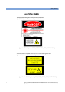
WARNING You MUST return instruments with malfunctioning laser modules to
an Agilent Technologies Sales/Service Center for repair and
calibration.
Line Power Requirements
The Agilent 81480A, Agilent 81680A, Agilent 81640A, Agilent 81682A,
Agilent 81642A, & Agilent 81689A Tunable Laser Modules operate
when installed in the Agilent 8164A Lightwave Measurement System.
The Agilent 81689A also operates when installed in the Agilent 8163A
Lightwave Multimeter or Agilent 8166A Lightwave Multichannel
System.
Operating Environment
The safety information in the Agilent 8163A Lightwave Multimeter,
Agilent 8164A Lightwave Measurement System, & Agilent 8166A
Lightwave Multichannel System User’s Guide summarizes the
operating ranges for the Agilent 81480A, Agilent 81680A,
Agilent 81640A, Agilent 81682A, Agilent 81642A, & Agilent 81689A
Tunable Laser Modules. In order for these modules to meet
specifications, the operating environment must be within the limits
specified for your mainframe.
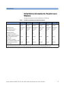
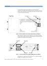
Input/Output Signals
CAUTION There are two BNC connectors on the front panel of the
Agilent 81480A, Agilent 81680A, Agilent 81640A, Agilent 81682A, and
Agilent 81642A; a BNC input connector and a BNC output connector.
There is one BNC connector on the front panel of the Agilent 81689A -
a BNC input connector.
An absolute maximum of ±6 V can be applied as an external voltage to
any BNC connector.
Storage and Shipment
This module can be stored or shipped at temperatures between
−40°C and +70°C. Protect the module from temperature extremes that
may cause condensation within it.