


Performance Tests Performance Test Instructions
64 Agilent 81480A and 81680A, 40A, 82A, 42A, & 89A Tunable Laser Modules User’s Guide,
Sixth Edition
NOTE The largest Maximum Deviation is the largest positive value and the
smallest Minimum Deviation is the largest negative value (largest
deviation above and below zero respectively).
12 Determine the Relative Wavelength Accuracy Result:
Subtract the Smallest Minimum Deviation from the Largest
Maximum Deviation. Record this value as the Relative Wavelength
Accuracy Result.
Absolute Wavelength Accuracy
13 From the measurements taken in the Relative Wavelength Accuracy
test, pick the largest absolute value from either the Largest
Maximum Deviation or the Smallest Minimum Deviation taken in
step 12 and note this value as Absolute Wavelength Accuracy.
Mode Hop Free Tuning
NOTE This section does not apply for Agilent 81689A Tunable Laser module.
14 Move to the Tunable Laser channel of the Agilent 8164A Lightwave
Measurement System and press [Menu].
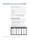
15 Set the menu parameters to the values shown in Table Table 5.
16 If you are using the Agilent 81480A, Agilent 81680A, or the
Agilent 81640A Tunable Laser module:
Connect the output fiber to Output 2, the High Power output.
Set <Optical Output> to <High Power (2)>.
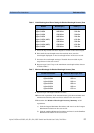
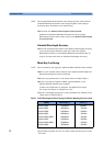
17 Set the wavelength and power of your Tunable Laser module to the
values given in Table Table 8.
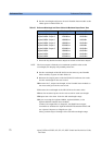
Table 8 Initial Wavelength and Power Settings for Relative Wavelength Accuracy Tests
Module Wavelength [λ] Power [P]
Agilent 81480A 1415.000 nm 0.00 dBm
Agilent 81680A 1460.000 nm −3.00 dBm
Agilent 81640A 1510.000 nm −3.00d Bm
Agilent 81682A 1460.000 nm −3.00 dBm
Agilent 81682A (#003) 1460.000 nm −4.50 dBm
Agilent 81642A 1510.000 nm −3.00 dBm
Agilent 81642A (#003) 1510.000 nm −4.50 dBm
Agilent 81689A 1525.000 nm −3.00 dBm