


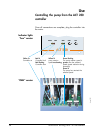

Use
Alcatel Vacuum Technology France - ACT 250 addendum
26
January 2001
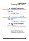
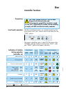
Controller functions
Precautions
Local mode operation
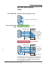
The Start and Stop functions use switches located on the
front panel of the “box” version and on the board for the
“OEM” version.
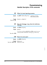
The “OEM” version of the ACT 250 has been
designed with electrical safety and
electromagnetic compatibility standards in mind.
It is the user’s responsibility to provide external shielding
to comply with EMC and electrical safety standards.
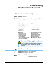
POWER FAULT SPEED
START STOP
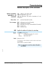
The pump’s operating status is shown by the state of the
“POWER” indicator (yellow) and the three “FAULT” (red)
and “SPEED” (yellow and green) indicators.
Indication of rotation
during operation
(controller on)
Pump
motor on
Pump
rotation
speed
State of indicators
Power
Yellow
Fault
Red
Speed
Yellow Green
Press button
START STOP
1 Before start-up
2 During start-up
3 Pump at nominal speed
5 Overload
7 Pumping stopped
0
1
0
0
0
0
0
0
0
1
NO
YES
YES
YES
NO
0
< selected
speed
= selected
speed
< selected
speed
0
6 Speed set point lowered
0 0 YES
> selected
speed
indicator off indicator on indicator flashing
4 Alert
Fault
Alert or fault
triggered
(see page 27 )
0 0
YES
NO
≤ selected
speed
0