


Installation Sheet
RDM-2INC Dual Incandescent Dimmer Module
2400 W (x2)
The RDM-2INC Dual Incandescent Dimming Module 2400 W (x2) incan-
descent dimmer is designed for use with the RDA series of enclosures, in
an AMX Lighting™ modular digital dimming system. It can dim incandes-
cent lights, cold-cathode, neon and two-wire dimmable ballasts. The mod-
ule's 120, 240, and 277 VAC ratings are CE, UL, and C-UL approved.
RDM-2INC UL and C-UL Ratings
• 120 VAC, 50/60 Hz, 2400 W
• 240/277 VAC, 50/60 Hz, 2400 W
Suggested Dimmed Loads
• Incandescent
• Low-voltage
• Neon, cold-cathode
• Two-wire, phase-controlled ballast
Specifications
• Dimensions (HW): 10.0" x 2.75" (25.4 cm x 6.99 cm)
• Phase dependant
• Use wires rated at 75°C (167°F)
• Torque terminals to 7 in-lbs. (0.8 N/M)
• Max. wire size: 10 AWG (4 mm²)
• Wire stripping length: 0.28" (7 mm)
• Weight: 6.5 lbs. (2.948 kg)
• BTU/hr: 600
• Control current: 45 mA @ 12 VDC per dimmer, 90 mA total
Caution: Pre-Installation Notes
• All Class 1 wiring must be connected to proper terminals.
• All control wiring must be connected to proper temrnials.
• Disconnect power while installing or connecting the unit.
• Keep top and bottom air vents clear at all times.
• Test loads for shorts before connecting.
• Use low voltage wires with a 300 volt rating or greater.
• Use field installed copper conductors.
• Run all low-voltage and control wires away from heat producing parts
of the dimmer.
• Each dimming circuit must have a separate neutral connection.
• All electrical ratings are for continuous duty.
• AC lighting loads only.
• For indoor use only.
• This module may require extra power from the AXlink connection or an
external power supply connected to the control card.
Connecting the RDM-2INC to the AMX Lighting Master
Lighting Application Drawing
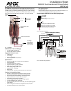
FIG. 1 RDM-2INC
Low-voltage
control wiring:
4-pin connectors
to AMX Lighting
master controller
350 µS choke
Dual 20 A power device
Line out
Line in (hot)
High-voltage
connections
Mounting
points
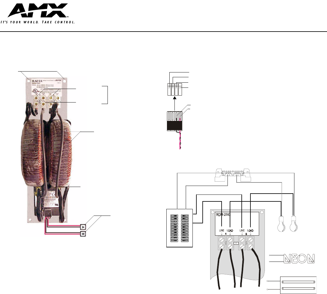
FIG. 2 RDM-2INC connections
FIG. 3 RDM-2INC wiring application
Pin 4 (GND)
Pin 3 (RLY)
Pin 2 (DIM)
Pin 1 (+12 V)
RDM-2INC four-pin module connector
4-pin plug from a RDM series module
Note: The 4-pin plugs from the module
connector to the 4-pin connector on the
master (black plug cover facing up).
2 (-)
1 (+)
Light A
Light B
(B) Load
(A) Load
(B) Line in (HOT)
(A) Line in (HOT)
(A) Neutral
(B) Neutral
Neutral
Load
Load
Neutral
Neon lights
(cold-cathode, on/off)
Two-wire dimmable
ballast
Circuit breaker
panel