


1. 120 volts may cause serious injury from electrical shock. Leave
power to all system components disconnected until installation
is complete
WARNING
MODEL 8028 DAMPER POWER DISTRIBUTION PANEL
INSTALLATION INSTRUCTIONS & APPLICATION SHEET
1. Installation must be done in accordance with the NEC and all
other applicable local codes.
2. To prevent excessive transformer heating, do not power more
than the recommended number of dampers to a transformer.
CAUTION
Voltage 24 VAC ±20%
Max. Damper Power Input per Zone 100VA max @ 24 VAC
Damper Fuse Size 5A Fast Acting (spare supplied)
Control Input Current Draw (Zone A and Zone B) 50 mA @ 24 VAC
Max. No. of Aprilaire Dampers per Zone 10 (refer to Diagram 3 on the back if there are
more than 10 dampers in a zone)
Max Wire Size 18 AWG
Application Temperature/RH 158°F / 90% RH (non-condensing)
SPECIFICATIONS
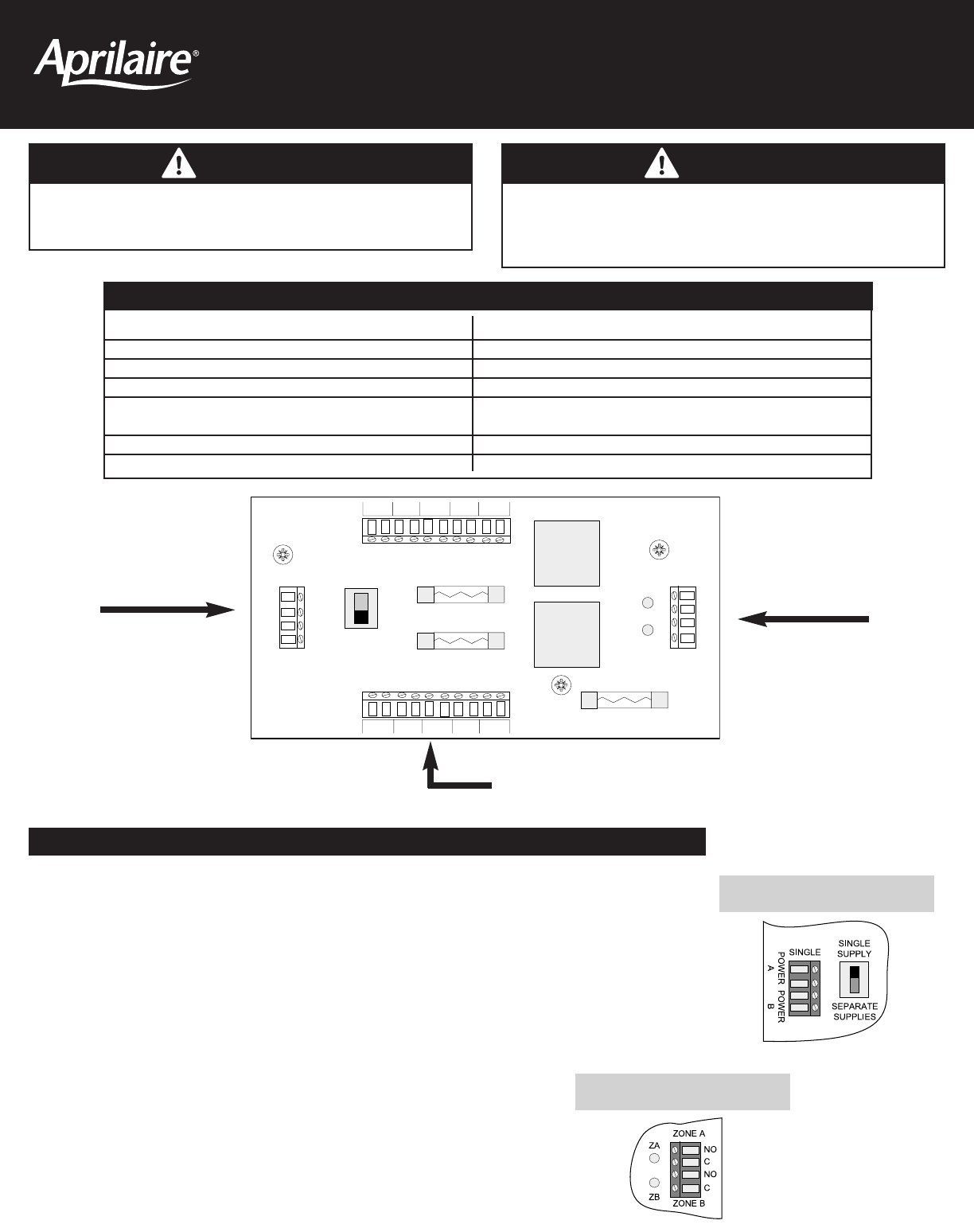
SWITCH SETTINGS AND LED’S
Set to SINGLE SUPPLY when used:
• in a two zone system when there are no more than 10 dampers in either ZONE A or ZONE B.
Size the transformer for the zone with the most dampers.
• when there are no more than 10 total dampers wired to ZONE A plus ZONE B. Size the transformer
for the total number of dampers connected to both zones.
When set to SINGLE SUPPLY, wire transformer to “POWER A” terminals. Refer to Diagram 2 on the
back for wiring.
Set to SEPARATE SUPPLIES for all other applications. Wire transformers to “POWER A” and “POWER B”
terminals. Refer to Diagram 1 on the back.
ZONE A
ZONE B
SINGLE
SINGLE
SUPPLY
SEPARATE
SUPPLIES
ZONE A – 5 AMP
ZONE B – 5 AMP
SPARE FUSE – 5 AMP
54321
ZONE B
DAMPERS
ZONE A
DAMPERS
12345
POWER
A
POWER
B
ZA
ZB
C
NO
C
NO
Damper Power Input(s)
from Transformers
Dampers Wired to ZONE A and ZONE B Terminals
Control Input(s) from
Zoned Comfort Control
Panel
Power Supply Switch
Zone LED’s
ZA LED lights when 24-volts is applied to the ZONE A control input.
ZB LED lights when 24-volts is applied to the ZONE B control input.