Installation
Note: Before installation, please inspect the Unit.
Make sure that nothing inside the package is damaged.
A. Connect to AC Utility Power
Plug in the AC cord to a wall outlet. Please make sure there are
no devices plugged into the Unit. Check to see whether the
“SITE WIRING FAULT” indicator is lit. If it is lit, please have the
utility wiring inspected by an electrician.
B. Charge the Battery
For best results, charge the battery for eight hours prior to initial use. The
Unit charges its battery whenever it is connected to the utility power.
C. Turn on the Unit
Turn on your Unit by depressing the “On/Off” button for approximately
two seconds. You will see the green indicator light come on.
D. Plug in Power Devices
Plug your devices into the AC outlets on the Unit. To use the Unit as a
master on/off switch, make sure all of the loads are switched on.
Caution: Never connect a laser printer or scanner to the
backup outlets along with other computer equipment.
A laser printer or scanner draws significantly more
power when in use than when idle. This may overload
the Battery Backup.
E. Connect the Phone/Fax/Modem Lines
1. Connect a single phone/fax/modem line into the surge-protected outlets
on the side of the Unit. The RJ11 modular outlets accept standard
single-line telephone connections.
2. Plug one end of the phone cable into your telephone wall jack and plug
the other end into the jack marked “IN”. You may now plug a phone, fax,
or modem into either of the two jacks marked “OUT”. (See Fig. 3)
Fig. 3
Note:
This connection is optional but highly recommended as phone/fax/
modem lines often carry dangerous surges and spikes. The Unit works
properly without a phone/fax/modem connection.
Caution:
The phone/fax/modem protection feature could be rendered inoperable
if improperly installed. Make sure that the telephone line from the wall is plugged
into the connector marked “IN”, and the devices to be protected (phone/fax/
modem) are plugged into the connector marked “OUT”.
F Connect the USB (Universal Serial Port) Communication
Port (See #4 on Fig. 2)
A USB port is provided to relay the signal to support Windows. To fully utilize
the Belkin Automatic Power Management Software, you will need to connect
the Unit to your computer. Connect the USB cable to the Unit, then connect the
other end to your computer’s USB port.
G. Install Belkin APM Software
a) System requirements
• 128 MB RAM of memory at least (256MB is recommended)
• 256 colors and 800 * 600 resolution or above display is recommended
• 160 MB of disk space or above
• An available communication port (RS-232 Serial Port or USB port) is needed
while connecting to UPS with a special connecting cable.
• For Mac OS X, Linux or Unix operating system, the user must have the access
authority as the super user
• TCP/IP protocol must be installed to support network management
• The user needs to have the access authority as the administrator
b) Platforms supported by Belkin APM Software
.
The following operating system (OS) is arranged by the alphabetical order:
Introduction
Thank you for purchasing the Battery Backup with Surge Protection (the
Unit). Each year, frequent natural and man-made power disturbances
disrupt the power supplied to your home or office electronics. These power
problems place your hardware, software, and data at risk. Belkin Battery
Backups provide an uninterruptible power supply (UPS) with advanced
features as the industry-leading solution.
Package Contents
You should have received the following:
1 – Battery Backup unit
1 – Installation CD containing Belkin Automatic Power Management Software
(the Belkin APM Software) for Windows
®
1 – USB Cable
1 – Phone-Line Cable
System Requirements
The Battery Backup can be used without the software with any computer using
up to a 17" CRT or LCD monitor. You do not have to have the software installed to
utilize the battery-backup outlets.
To fully utilize the Battery Backup and its software, your computer must be running
one of the following operating systems: Windows XP / 2003 / 2000 / ME / 98 / NT 4.0
(SP6) or Linux, and have a USB port.
Overview | Features and Functions
Before installation, please inspect the Unit upon receipt. Make sure that
nothing is damaged.
Your Battery Backup features three LED indicators. Each is marked by a
power icon; please familiarize yourself with this chart, as it will assist you in
the use of your Battery Backup. (See #4 on Fig. 1)
3. The “On/Off” button has four functions: (See #3 on Fig. 1)
1. Turns on the Unit. Depress button at least two seconds. The green
light illuminates.
2. Cold start function. If the battery is charged, the Unit will work without
being plugged into an outlet. Depress and hold the key for at least two
seconds to turn on the Unit.
3. Silence function. During “On Battery Mode”, the audible sound
can be turned “ON” or “OFF” by depressing the switch for less
than 1.5 seconds.
4. Battery test function. During “On-Line Mode”, depressing the switch
for less than 1.5 seconds causes the Unit to perform a battery test in
backup mode.
Overview | Side Panel
1. AC Input Power Cord (See #1 on Fig. 2)
Provides power to your Battery Backup.
2. Phone/Fax/Modem Surge Protection (See #2 on Fig. 2)
The phone/fax/modem lines are surge-protected. There are one input jack
and two output jacks. This allows you to split one telephone connection to
two separate devices.
3. AC Breaker (Circuit Breaker; see #3 on Fig. 2)
Should a power overload occur, the circuit breaker triggers the Unit to turn
off AC power. To restore power, depress the “circuit breaker” button to reset,
then depress the “Power” button.
4. USB Communication Port (See #4 on Fig. 2)
The Unit features a USB communication port. Installation of the cable and the
Bulldog Plus Software, which allows the Unit to connect to your computer, is
optional. The Unit will provide backup power whether or not the cable and
software are installed; however, without them you will be unable to utilize the data
management product features.
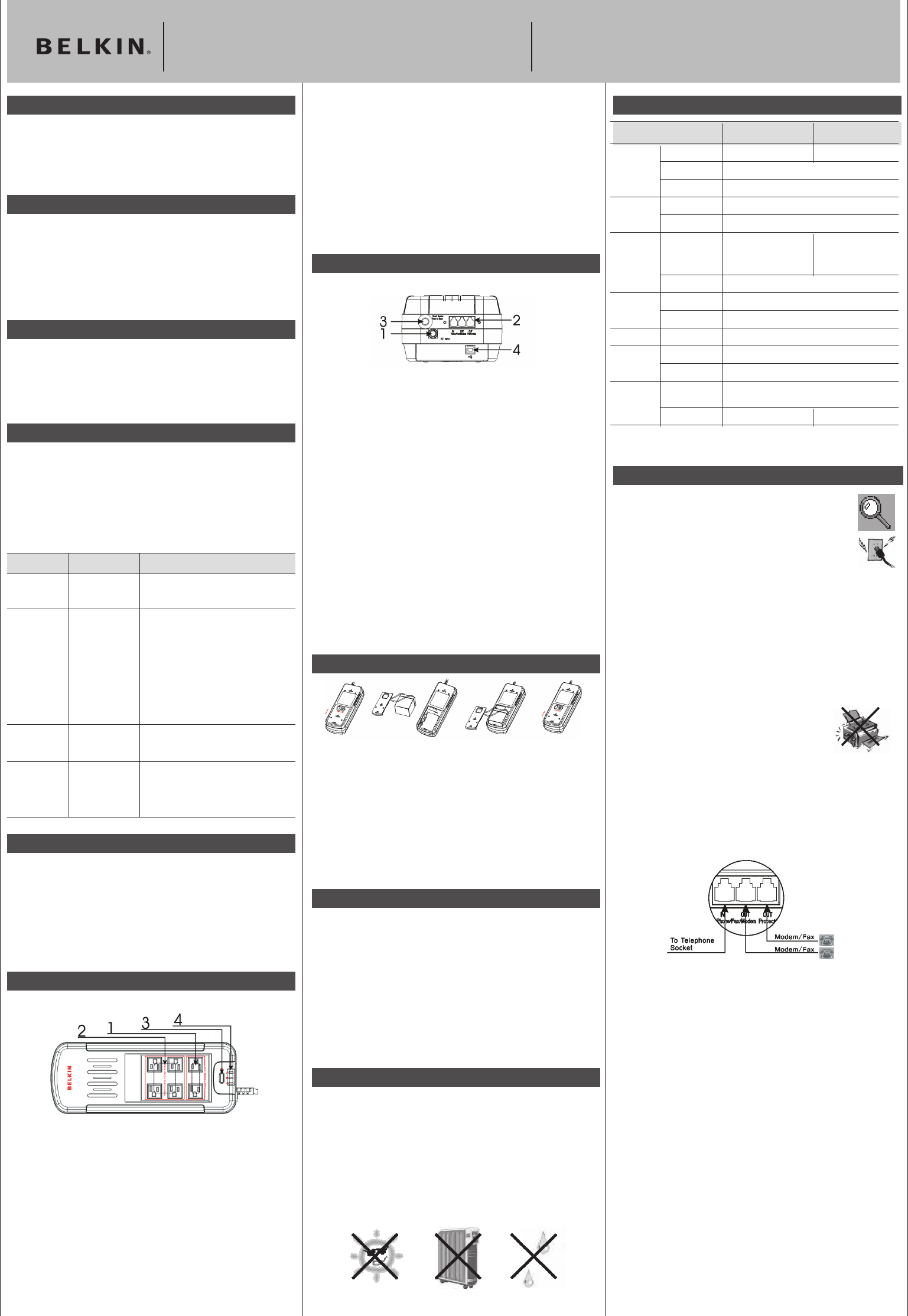
Battery Replacement Procedure
Replacement requires removing the battery cover plate on the back or
bottom of the Battery Backup. No tools are needed. To replace the battery:
1. Push the connector in the arrowhead direction.(Fig.1)
2. Remove the battery cover plate and the battery from the Unit(Fig.2)
3. Disconnect the insulated connectors from the battery terminals, and replace
the new battery pack. (Fig. 3)
4. Close the battery cover plate, then lock the connector. (Fig.4)
.
Overview | Alarms
Backup (Slow Alarm)
When the Unit is in “backup” mode (running on battery), the YELLOW LED
illuminates and the Unit emits an audible alarm. The alarm stops when the
Unit returns to normal online operation.
Low Battery (Rapid Alarm)
In “backup” mode, when the battery energy runs low, the Unit beeps rapidly
until it either shuts down from a depleted battery or returns to normal
online operation.
Fault (10 Seconds Continuously)
When the Unit fails, it emits an audible alarm continuously for 10 seconds to
warn of a fault condition. Disconnect the equipment prior to checking it.
Overview | Storage
Storage Conditions
Store the Unit covered and upright in a cool, dry location with its battery fully
charged. Before storing, charge the Unit for at least six (6) hours.
Extended Storage
During extended storage in environments where the ambient temperature
is +5° F to +86° F, charge the Unit’s battery every six (6) months. During
extended storage in environments where the ambient temperature is +86° F
to +113° F, charge the Unit’s battery every three (3) months.
Note:
Overview | Important Safety Instructions
Please save this User Manual!
It contains important operating instructions and warranty information
pertaining to your Battery Backup.
Please save or recycle the packaging materials!
The Unit’s packaging was designed with great care to provide protection
during shipment and delivery. These materials are invaluable if you ever have
to return the Unit for service. Damage sustained during transit is not covered
under the warranty.
Overview | Top Panel
1. Surge-Protected-Only Outlets (See #1 on Fig. 1)
These outlets do not provide battery power during an outage. Do not
plug surge protectors or power strips into the battery-backup outlets
(i.e., daisy-chaining).
Equipment such as computer peripherals, printers, fax machines, or desk
lamps may be plugged into these outlets. The On/Off button does not control
these outlets.
2. Battery-Backup Outlets (See #2 on Fig. 1)
Only data-sensitive equipment such as a computer, monitor, and external
drive should be plugged into these outlets. Battery power is automatically
provided in case of a power outage. Power (AC or battery) is not supplied to
these outlets when the Unit is switched off. (Do not plug surge protectors or
power strips into the battery-backup outlets.)
Caution: Never connect a laser printer or scanner to the backup outlets
along with other computer equipment. To do so might overload the Unit.
Overview | Technical Specifications
Chart 1
Indicator Condition Meaning
On-Line ○ Solid Green The Unit is operating and supplying the utility
power to connect loads.
On-Battery
*
Flashing Yellow
Low Battery
Replace Battery
UPS Fault ○ Solid Yellow
Site Wiring Fault ○ Solid Red
When the Unit is operating from battery:
1. The light blinks every 10 seconds if the
Unit is operating on battery mode.
2. The light illuminates rapidly every
1 second if the Unit’s battery is very
nearly depleted.
When the Unit is operating and supplying
the utility power to connect loads, the LED
flashes and the buzzer emits a sound every
1 minute to indicate the Unit’s battery needs
to be replaced.
The “SITE WIRING FAULT” LED illuminates
when one of the following conditions exist:
1. Open or high resistance ground
2. Hot and neutral polarities reversed
The LED lights steadily and the buzzer
beeps for 10 seconds if a
battery fault is found.
Fig. 1
Fig. 2
Model F6H375-USB F6H550-USB
z
Input Rated Capacity 375VA/200W 550VA/300W
Rated Voltage 104–137VAC
Phase/Freq. Single-phase 60Hz
Output Voltage Step wave
Frequency 60Hz
Battery Backup Time Desktop Desktop computer +17"
computer
monitor 13 min.
+15" monitor
10 min.
Recharge Time 16 hours to 90%
Environment Temperature 0~
40°C
Humidity 0~90%
Safety Safety UL1778 / c-UL
Regulation EMI FCC Class B
EMS IEEE C62.41 category A/IEC1000-4-5 / Level 2
Appearance Dimensions 134 x 89 x 357mm
(W * H * D)
Net Weight 2.9kg. 3.1kg.
All specifications are subject to change without prior notice.
Battery Backup with Surge Protection User Manual F6H375-USB, F6H550-USB
Fig. 1 Fig. 2 Fig. 3 Fig. 4


