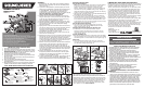
SERVICE INFORMATION
Black & Decker offers a full network of company-owned and
Authorized Service locations throughout North America. All Black &
Decker Service Centers are staffed with trained personnel to provide
customers with efficient and reliable power tool service. Whether you
need technical advice, repair, or genuine factory replacement parts,
contact the Black & Decker service location nearest you. To find
your local service location, refer to the yellow page directory under
“Tools—Electric” or call: 1-800-54-HOW-TO.
I
MPORTANT SAFETY INSTRUCTIONS
1. Do not load with more than 550 pounds.
2. Do not apply an unbalanced load which could cause the work center to tip over.
3. Do not use the work center as a stepladder or standing platform. Do not use the
lower platform as a step when the work center is in “Workbench” position. The
footboard is a foot REST only.
4. Do not store work center outdoors or in a damp location.
5. Avoid applying excessive force when clamping with the swivel pegs.
6. Be sure that the legs are fully open (for workbench height) and be sure that the
table locks in position.
7. When using a power tool with the work center, follow the safety instructions in
the tool’s instruction manual.
8. Always wear safety glasses when operating power tools.
9. An even pressure of the vise jaws on the workpiece is essential. Tighten both
crank handles uniformly.
10. When assembling your work center, use only the special plastic socket wrench
provided. Use of other wrenches or sockets can damage your work center.
SAVE THESE INSTRUCTIONS FOR FUTURE USE.
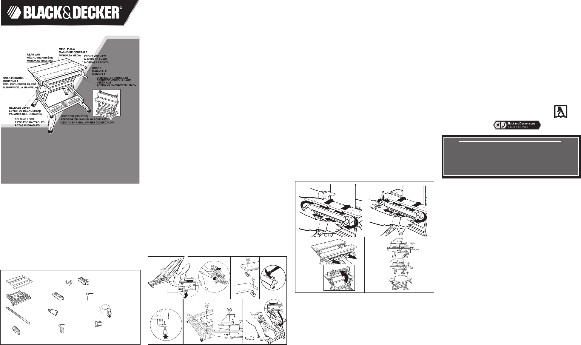
ASSEMBLY:
1. The Workmate
®
425 work center comes partially assembled.
Empty the carton completely onto the floor and identify all the
components. (Fig 1)
2. Tip the front of the Workmate
®
up and rest it against your knee as
shown in Fig. 2. Pull upwards on both left and right release levers
to unlock Workmate
®
(Fig. 2a). Using one hand, push the top
of the Workmate
®
up and away from you while holding the
footrest with your other hand until the frame locks in place. (Fig.2b)
Note: New Workmates
®
are stiff and require more
effort to raise into the locked working position.
3. Assemble two top blocks to the underside of the rear jaw by
fitting the raised posts on the top blocks into the smaller holes
of the rear jaw. Insert bolts through the rear jaw and into top
blocks and tighten with supplied wrench. (Fig 3)
4. Assemble top blocks to middle jaw the same as rear jaw. (Fig 4)
5.
With one hand firmly holding the vise jaw assembly, to the front
of the Workmate, remove one of the white plastic shipping
retainers and discard.
6. Aligning the hole in the vise crank with the hole in the vise screw,
push the vise crank onto the vise screw end (protruding from the
front of the vise jaw bracket). Using a hammer, drive the
supplied pin into the aligned holes. Repeat this procedure for
the installation of the other vise crank. ( Fig 5)
7. Complete the assembly by pushing the snap-in knobs into the
holes in the vise cranks. (Fig 6)
8. Install the front vise jaw on top of the top blocks so that the small
holes at each end of the vise jaw fit down over the posts on the
top side of the blocks. With the jaw positioned as described
above insert into the frame as shown. Insert a bolt into the holes
in the jaw and tighten them securely into the holes in the pivot
nut. Use the socket wrench provided. (Fig 7)
9. Select the rear vise jaw, and the two rear top blocks. Position the
rear top blocks on the frame rails so that the tab ears in the
bottom of the blocks fit into the key holes of the frame rail.
Position the top blocks so their raised posts are toward the rear
of the frame. Now install the rear vise jaw so that the small holes
in the ends of the jaw fit over the raised posts on the top blocks
you just installed. (Fig 8)
10. Insert the remaining two bolts, into the holes in the jaw and
through the top blocks into the raised posts of the vise guides.
The holes in the rear blocks are not threaded so you will feel
resistance as you cut threads into them.
11.
To close up the Workmate
®
for storage, pull upward on the two
release levers to unlock the Workmate
®
. While holding the
levers up pull back and down to close the Workmate
®
. (Fig 9)
Fig. 13
Fig. 14
Fig. 15
IMPORTANTES MESURES DE SÉCURITÉ
1. Ne jamais placer une charge supérieure à 550 lb sur l’étau-établi.
2. Ne jamais placer sur l’étau-établi une charge mal équilibrée qui
pourrait le faire basculer.
3. Ne jamais se servir de l’étau-établi comme marchepied ni
comme plate-forme. Ne pas monter sur la plate-forme inférieure
lorsque l’étau-établi est en position d’établi. Le repose-pied sert
seulement à se REPOSER les pieds.
4. Ne pas ranger l’étau-établi à l’extérieur ni dans un endroit humide.
5. Éviter de trop serrer les mâchoires des mordaches orientables.
6. S’assurer que les pieds sont bien étirés (en position d’établi) et que
la table est enclenchée en place.
7. Respecter les consignes de sécurité contenues dans les guides
d’utilisation des outils électriques utilisés avec l’étau-établi.
8. Toujours porter des lunettes de sécurité lorsqu’on utilise des
outils électriques.
9. Les mâchoires doivent exercer une pression uniforme sur la
pièce à ouvrer, il faut donc les serrer également.
10. Pour le montage de l’étau-établi, utiliser seulement la clé à
douille spéciale en plastique fournie. Toute autre clé
pourrait l’endommager.
CONSERVER CES MESURES À TITRE DE RÉFERENCE.
ASSEMBLAGE
1. L’étau-établi Workmate
®
425 est assemblé en partie. Sortir tout le
contenu du carton d’emballage et vérifier si tous les éléments y sont (fig. 1)
2. Faire basculer l’avant de l’étau-établi vers le haut et le faire reposer
sur ses genoux de la manière illustrée à la figure 2. Tirer vers le
haut les deux leviers de dégagement afin de déverrouiller l’étau-
établi (fig. 2a). À l’aide des deux mains, pousser le haut de l’étau-
établi vers le haut en l’éloignant de soi tout en retenant le repose-
pied de l’autre main jusqu’à ce que le châssis s’enclenche (fig. 2b).
NOTE! Les nouveaux étaux-établis sont rigides et il faut exercer un
grand effort pour les enclencher en position de travail.
LIMITED TWO-YEAR HOME USE WARRANTY
Black & Decker (U.S.) Inc. warrants this product for two years against
any defects in material or workmanship. The defective product will be
replaced or repaired at no charge in either of two ways:
The first, which will result in exchanges only, is to return the product
to the retailer from whom it was purchased (provided that the store
is a participating retailer). Returns should be made within the time
period of the retailer’s policy for exchanges (usually 30 to 90 days
after the sale). Proof of purchase may be required. Please check
with the retailer for their specific return policy regarding returns that
are beyond the time set for exchanges.
The second option is to take or send the product (prepaid) to a Black
& Decker owned or authorized Service Center for repair or
replacement at our option. Proof of purchase may be required. Black
& Decker owned and authorized service centers are listed under
“Tools-Electric” in the yellow pages of the phone directory.
This warranty does not apply to accessories. This warranty gives you
specific legal rights and you may have other rights which vary from
state to state. Should you have any questions, contact the manager
of your nearest Black & Decker Service Center.
This product is not intended for commercial use.
FEATURES & APPLICATIONS:
One Handed Clamping:
Note: A vise screw clutch allows moving the front vise jaw parallel or
at the same angle to the rear jaw using either one of the crank
handles. Turning both crank handles at the same time (same
direction, different speed or opposite to each other) disengages the
vise screw clutch (causing a normal “clicking” sound), allowing for
independent movement of left and right crank handles. For clamping
pressure, turn the crank handles clockwise.
1. Hold work with one hand and turn one crank handle till work is
held snugly by the vise jaws.
(Fig 10)
2.
Turning both crank handles clockwise after securing material with
One Handed Clamp
TM
provides final clamping pressure. To remove
work from vise, turn crank handles counter-clockwise. Note: Turning
a crank handle to quickly may cause the transmission belt to come
off the sprocket hub. In this event the transmission belt can be easily
stretched back onto the sprocket hub.
(Fig 11)
One Handed Vertical Clamping:
3.
Pull vertical locking bar toward yourself and lift front vise jaw
until it is in vertical, locked position. Note: Rear jaw must be in
middle “keyhole” position.
(Fig 12)
Changing the Indexed Position of the Rear Jaw:
4. Install rear jaw in one of three possible indexed “keyhole”
positions by inserting the indexing lug into a keyhole in the vise
jaw bracket. Secure the rear jaw by moving rear jaw to the back
of the key hole.
(Fig 13)
Installing the Middle Jaw:
5.
With front jaw cranked to the front of the work center, insert the indexing
lugs of the middle jaw into the front keyholes. Rear jaw is then installed
in the back keyholes. Turn crank handle clock wise to tighten.
(Fig 14)
Swivel Pegs:
6. The four supplied swivel pegs can be used in any of the holes
in the front and rear jaws. The pegs are used to extend the size of
your Workmate’s holding capacity.
(Fig 15)
Thank you for choosing Black & Decker! To register your new product go to
www.BlackandDecker.com/NewOwner
PLEASE READ BEFORE RETURNING THIS PRODUCT FOR ANY REASON.
If you have a question or experience a problem with your Black & Decker purchase,
go to http://www.blackanddecker.com/instantanswers
If you can’t find the answer or do not have access to the Internet,
call 1-800-544-6986 from 8 a.m. to 5 p.m. EST Mon. - Fri. to speak with an agent.
Please have the catalog number available when you call.
SAVE THIS MANUAL FOR FUTURE REFERENCE.
VEA EL ESPANOL EN LA CONTRAPORTADA.
INSTRUCTIVO DE OPERACIÓN, CENTROS DE SERVICIO Y PÓLIZA DE GARANTÍA.
ADVERTENCIA: LÉASE ESTE INSTRUCTIVO ANTES DE USAR EL PRODUCTO.
Workmate
®
425 tYPe 6
INSTRUCTION MANUAL
CATALOG NUMBER
WM425 TYPE 6
Fig.1
4 Swivel Pegs
4 mordaches orientables
4 Topes giratorios
2 Snap-in Knobs
2 poignées de manivelle
2 Perillas a presión
4 Rubber Feet
4 pattes de caoutchouc
4 Patas de goma
6 Bolts
6 boulons
6 Tornilos
Wrench
Clé
Llave
4 Top Blocks
4 blocs supérieurs
4 Bloques superiores
2 Cranks
2 manivelles
2 Manivelas
2 Pins
2 tiges
2 Pernos
Workmate Frame
Châssis de l'étau-établi
Estructura
3 Jaws
3 mâchoires
3 mordazas
2 front Blocks
2 blocs avant
2 bloques frontales
2 Vise Screws
2 tiges filetées
2 Tornillos de prensa
2 Pivot Nut
2 écrous de pivot
2 Tuercas de giro
Fig. 6
Fig. 7. Fig. 8
Fig. 3
Fig. 4
Fig.2
Fig.2a
Fig.2b
Fig. 5
Fig. 9
Imported by:
Black & Decker (U.S.) Inc.,
701 E. Joppa Rd.
Towson, MD 21286 U.S.A.
See ‘Tools-Electric’
– Yellow Pages –
for Service & Sales
AVANT DE RETOURNER LE PRODUIT, PEU IMPORTE LA
RAISON, PRÉRE DE COMPROSER LE 1 800 544 6986
Modèle WM425
GUIDE D’UTILISATION
"
CLICK
CLICK"
Fig. 12
Fig. 10
Fig. 11