


6
RECOMMENDED MINIMUM WIRE SIZE
FOR EXTENSION CORDS
TOTAL LENGTH OF CORD
25 FT. 50 FT. 75 FT. 100 FT. 125 FT. 150 FT. 175 FT.
7.6 M 15.2 M 22.9 M 30.5 M 38.1 M 45.7 M 53.3 M
WIRE SIZE AWG
18 18 16 16 14 14 12
9. Use only the supplied charger when charging your tool. The use of any other
charger could damage the drill or create a hazardous condition.
10. Use only one charger when charging.
11. Do not attempt to open the charger. There are no customer serviceable parts
inside. Return to any authorized Black & Decker service center.
12. DO NOT incinerate the battery packs even if they are severely damaged or
completely worn out. The batteries can explode in a fire.
13. A small leakage of liquid from the battery cells may occur under extreme usage,
charging or temperature conditions. This does not indicate a failure. However, if the
outer seal is broken and this leakage gets on your skin:
a. Wash quickly with soap and water.
b. Neutralize with a mild acid such as lemon juice or vinegar.
c. If the battery liquid gets in your eyes, flush them with clean water for a minimum of
10 minutes and seek immediate medical attention. MEDICAL NOTE: The liquid is a
25-35% solution of potassium hydroxide.
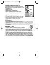
Charging Procedure
Your charger is designed to use standard 120 volt AC, 60 Hz power. Do not use DC or
any other voltage. Charge time is 60 minutes depending on battery pack type and
condition.
1. Plug the charger into an appropriate outlet. NOTE: Do not charge by
means of an engine generator or DC power source. Use only
120V AC.
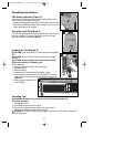
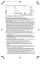
2. Insert the battery pack into the charger (Figure 1). Be sure the pack is
fully seated in the charger. The red (charging) light will blink
continuously indicating that the charging process has started.
3. The completion of charge will be indicated by the red light remaining ON
continuously. The battery pack is fully charged and may be used at this
time or left in the charger.
4. Unplug charger, and remove the battery pack. Place the battery in
the tool and be certain that it is inserted fully into the tool
cavity until it “clicks” into place.
NOTE: To remove the battery pack from the product, press down
on the release button on the back of the battery (Figure 2) and
pull out.
Replace Pack
The charger is designed to detect certain problems that can arise with
battery packs which would be indicated by the red light flashing at a fast rate. If this
occurs, re-insert battery pack. If problem persists, try a different battery pack to determine
if the charger is OK. If the new pack charges correctly, then the original pack is defective
and should be returned to a service center for recycling. If the new battery pack gives the
same trouble indication as the original, have charger tested at an authorized service
center.
Wall Mounting (Figure 2A)
A hole is provided in the center of the charger for mounting on a
vertical surface.
2
1
2A
90514937 BDBN1202 1/18/07 9:14 AM Page 6