


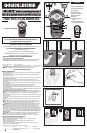
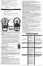

Installing the Battery
Ensure laser on/off switch (A) is in the full off position by moving laser button to "O" position.
Remove the battery compartment cover (H). Insert 2 fresh 1.5 volt AA alkaline batteries
making sure to match (+) and (-) terminals correctly. Replace battery compartment cover.
WARNING: Batteries can explode, or leak, and can cause injury or fire. To reduce this
risk:
• Carefully follow all instructions and warnings on the battery label and package. • Always
insert batteries correctly with regard to polarity (+ and -), marked on the battery and the
equipment. • Do not short battery terminals. • Do not charge batteries. • Do not mix old
and new batteries. Replace all of them at the same time with new batteries of the same
brand and type. • Remove dead batteries immediately and dispose of per local codes. •
Do not dispose of batteries in fire. • Keep batteries out of reach of children. • Remove
batteries if the device will not be used for several months.
“Transporting batteries can possibly cause fires if the battery terminals inadvertently come
in contact with conductive materials such as keys, coins, hand tools and the like. The US
Department of Transportation Hazardous Material Regulations (HMR) actually prohibit
transporting batteries in commerce or on airplanes (i.e. packed in suitcases and carryon
luggage) UNLESS they are properly protected from short circuits. So when transporting
individual batteries, make sure that the battery terminals are protected and well insulated
from materials that could contact them and cause a short circuit.”
LOW BATTERY INDICATOR
A battery energy level indicator is displayed in the lower left hand corner of
the display screen.
Operating Instructions
NOTE: Detecting elements for wood and metal studs and AC Wires are
located in the lower part of the unit.
STUD DETECTION
For stud detection through up to 3/4 inch (19mm) thick drywall.
1). Hold unit straight up and down and place flat against wall as shown in Figure 1.
2). Press in and hold the detector on/off button (B). LCD screen (D) will light and detector will
run initialization process.
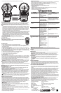
3). READY message will appear on LCD screen and the unit will beep once to indicate it is
calibrated and ready for detection.
4). Slide unit slowly, Figure 2, horizontally across surface of wall without lifting or tilting. When
the STUD FOUND message appears on the LCD screen, slow down and keep sliding until
EDGE message appears and beep sounds as shown in Figure 3. This is the stud edge. Mark
this spot (at arrow on lower part of unit).
5). Keep moving past mark until EDGE and STUD FOUND disappear.
6). Continue holding detector button and reverse direction.
7). Find and mark other stud edge, following step 4).
8). Center of the stud is between marks.
AC WIRE SENSING
Test on a known “live” AC wire before each use. For AC Detection up to 1-1/2 inches (38mm)
from the surface. The sensor detects AC voltage and will identify only live wires. AC voltage
detection feature works continuously when detecting studs. It assists in identifying when the
sensor is near live AC wiring and detector button (B) is depressed. Once AC voltage has
been detected AC wire indicator LED (C) will light.
If the unit is calibrated close to AC wire, it may decrease AC wiring sensor sensitivity. Static
charge may spread detection 12 inches (30.4cm) on both sides of wire.
WARNING: Occasionally, pipes and electrical wiring may not be detected by this product.
Observe caution when cutting or drilling into areas that may contain concealed pipes or
wiring. The sensor will not detect live wires inside metal pipe or metal conduit, behind
metallic wall covering, or behind some plywood or other dense materials.
Use caution if area has plywood, thick wood backing behind drywall, or thicker than normal
walls.
WARNING: Always turn off the power when working near electrical wires, electric
shock may result.
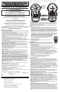
AUTO LEVELING LASER LINES
Operation of Laser: Place unit flat against wall as shown in Figure 1. Move laser on/off
button (A) to "I" position to actuate the auto leveling horizontal laser lines.
HANGING ON DRYWALL SURFACES ONLY
Hands Free Operation of Laser: To hang the unit on a wall, remove the orange protective
cap from the drywall pin (F) and store it on the cone as shown in Figure 4. Push pin into
drywall (Figure 5). When pressing pin into drywall, make sure it is straight and seated firmly.
Hang the laser on the cone as shown in Figure 6 and check to make sure that the unit is
secure on the wall. Figure 7 illustrates a typical application for the laser when it is wall
mounted.
CAUTION: Pin is sharp and should be handled with care. The drywall pin should always be
pushed in by hand and never driven by a hammer. Replace protective cap after each use.
NOTE: The pin is only for use on drywall NOT other surfaces including plaster.
HANGING ON OTHER SURFACES
Hands Free Operation of Laser: For surfaces other than drywall, the (key hole) hanging
cone (E) can be used with a standard nail or screw in a predrilled hole. To use the keyhole
hanging cone, place it over a nail or screw on a vertical surface with the narrow portion of the
opening pointing upward. Push the laser onto the hanging cone until it snaps into place. To
remove the laser, lift it slightly and pull it straight off. The unit can also be used with the
hanging cone attached to the back and then hanging the unit on the nail or screw. Make sure
it is straight and seated firmly on the cone and that the unit is secure on the wall.
DANGER: Laser Radiation, avoid direct eye exposure.
Helpful Hints
• If the laser light becomes dim or is no longer visible when the switch is in the on position
check or change the battery.
• The laser lines are only level on the wall against which the unit is held or hung. The short
line visible on any adjacent wall is not level.
• The laser unit is a wall use tool only and only generates level lines when held against a
vertical surface.
• The laser unit is equipped with a pendulum lock that stops pendulum motion when the laser
on/off switch is moved to the off position.
• If the laser on/off switch is pushed part way to the on position, the laser lines may be on
while the pendulum lock is still engaged.
• Hold stud sensor straight up and down.
For your convenience and safety, the following labels are on your laser.
Helpful Hints (Con’t).
• Because studs are normally spaced 16 inches or 24 inches apart and are 1-1/2 inches wide,
beware of anything closer together or of a different width. Doors and windows are
constructed with studs and headers which are closer together.
• When using unit over a stucco wall, place a piece of cardboard over the surface to help
provide a smooth motion across the wall.
• Avoid materials which have inconsistent density such as:
• Carpeting and padding
• Ceramic floor tile
• Wallpaper containing metallic foils or fibers. Generally, surfaces covered with regular
wallpaper or fabric will scan with no difference in function.
• Walls that are freshly painted and are still damp.
• Excessively thick plaster and lath.
Storage
Always store this product indoors and in its protective case.
Maintenance
Use only mild soap and damp cloth to clean the tool. Never let any liquid get inside the tool;
never immerse any part of the tool into a liquid.
IMPORTANT: To assure product SAFETY and RELIABILITY, repairs, maintenance and
adjustment (other than those listed in this manual) should be performed by authorized service
centers or other qualified service organizations, always using identical replacement parts.
Accessories
Recommended accessories for use with your tool are available from your local dealer or
authorized service center. If you need assistance regarding accessories, please call:
1-800-544-6986.
WARNING: The use of any accessory not recommended for use with this tool could be
hazardous.
SERVICE INFORMATION
All Black & Decker Service Centers are staffed with trained personnel to provide customers
with efficient and reliable power tool service. Whether you need technical advice, repair, or
genuine factory replacement parts, contact the Black & Decker location nearest you. To find
your local service location, refer to the yellow page directory under "Tools—Electric" or call: 1-
800-544-6986 or visit www.blackanddecker.com
FULL TWO-YEAR HOME USE WARRANTY
Black & Decker (U.S.) Inc. warrants this product for two years against any defects in material
or workmanship. The defective product will be replaced or repaired at no charge in either of
two ways.
The first, which will result in exchanges only, is to return the product to the retailer from whom it
was purchased (provided that the store is a participating retailer). Returns should be made
within the time period of the retailerʼs policy for exchanges (usually 30 to 90 days after the
sale). Proof of purchase may be required. Please check with the retailer for their specific return
policy regarding returns that are beyond the time set for exchanges.
The second option is to take or send the product (prepaid) to a Black & Decker owned or
authorized Service Center for repair or replacement at our option. Proof of purchase may be
required.Black & Decker owned and authorized Service Centers are listed under
"Tools-Electric" in the yellow pages of the phone directory.
This warranty does not apply to accessories. This warranty gives you specific legal rights and
you may have other rights which vary from state to state or province to province. Should you
have any questions, contact the manager of your nearest Black & Decker Service Center. This
product is not intended for commercial use.
FREE WARNING LABEL REPLACEMENT: If your warning labels become illegible or are
missing, call 1-800-544-6986 for a free replacement.
LATIN AMERICA: This warranty does not apply to products sold in Latin America. For
products sold in Latin America, check country specific warranty information contained in the
packaging, call the local company or see the website for warranty information.
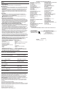
TECHNICAL SPECIFICATIONS OF LASER LEVEL:
Laser Diode Wavelength: 650 ± 5 nm (red color)
Laser Class: Class IIIa
Working Range: Up to 20 feet (depends on light conditions)
Leveling Accuracy: ±1/8 inch (3 mm) @ 10 feet (3 m)
Auto Leveling Range: ±4.5°
Auto Leveling Lines Settling Time: <5 sec
Batteries: 2 AA Alkaline (included)
Voltage: 3 Volt
Operating Temperature: 50°F (10°C)- 104° F (40°C)
L
ASER RADIATION. AVOID DIRECT EYE EXPOSURE.
R
ADIACIÓN LÁSER. EVITE LA EXPOSICIÓN DIRECTA DE LOS OJOS.
MAXIMUM OUTPUT POWER< 5mW@633nm-670nm CLASS IIIa LASER PRODUCT. THIS PRODUCT
COMPLIES WITH THE APPLICABLE REQUIREMENTS OF 21CFR PARTS 1040.10 AND 1040.11.
LÁSER CLASE IIIa CON MÁXIMA POTENCIA DE SALIDA < 5mW@633nm-670nm. ESTE PRODUCTO
CUMPLE CON LOS REQUISITOS APLICABLES DE LAS PIEZAS 1040.10 Y 1040.11 DE 21CFR.
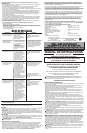
DANGER PELIGRO
Possible Cause
• Weak battery.
• Nothing to detect in that
area.
• Check mode. May
have been calibrated
over a stud.
Solution
• Replace with fresh battery.
•
Start again moving farther to
e
ither side.
Problem
• Unit not detecting any
studs in search area.
• Because studs are normally
spaced 16 inches or 24 inches
a
part and are 1-1/2 inches wide,
beware of anything closer together
or of a different width.
• Unit found too many
studs in search area.
• Detects other objects
besides studs.
• Electrical wiring and
metal or plastic pipes
may be near or touching
back surface of wall.
TT
TT
RR
RR
OO
OO
UU
UU
BB
BB
LL
LL
EE
EE
SS
SS
HH
HH
OO
OO
OO
OO
TT
TT
II
II
NN
NN
GG
GG
• Replace with fresh battery.
• Be sure that the unit is as straight
up and down as possible.
• Laser does not project
on wall.
• Weak battery.
• The self leveling range
of the unit is +/-5
degrees, if the unit is not
held within 5 degrees of
vertical, the laser lines
will not project on wall.
• Laser projects on wall
but lines are not level.
• Wall on which the unit
is mounted or held must
be within +/- 5 degrees
o
f vertical for the self
leveling mechanism to
function correctly. If this
is exceeded, the lines
will still project but may
not be level.
• The laser on/off switch
must be pushed to the
full on position.
• Use the unit against vertical walls
only, lines will not be level on
sloped walls or other non-vertical
surfaces.
• Be sure laser on/off switch is in
the full on position.
• Replace with fresh battery.
• If a switch controls an outlet, make
sure the it is ON for detection.
• You suspect electrical
wires, but do not detect
any.
• Weak battery.
• If wires are shielded
behind metallic wall
coverings, or in metal
c
onduit, the sensor will
not be able to detect
them.
•
The wires may not be
“
live”.
• Wires may be too deep
to sense.
• Use caution if area has
plywood, thick wood
backing behind drywall,
o
r thicker than normal
walls.
WARNING: Always turn off the power when working near electrical wires.
See ‘Tools-
Electric’
– Yellow Pages –
for Service &
Sales
Imported by
Black & Decker (U.S.) Inc.,
701 E. Joppa Rd.
Towson, MD 21286 U.S.A.
LASER RADIATION. AVOID DIRECT EYE EXPOSURE.
R
ADIACI” N L¡ SER. EVITE LA EXPOSICI”N DIRECTA DE LOS OJOS.
MAXIMUM OUTPUT POWER< 5mW@633nm-670nm CLASS IIIa LASER PRODUCT. THIS PRODUCT
COMPLIES WITH THE APPLICABLE REQUIREMENTS OF 21CFR PARTS 1040.10 AND 1040.11.
L¡ SER CLASE IIIa CON M¡ XIMA POTENCIA DE SALIDA < 5mW@633nm-670nm. ESTE PRODUCTO
CUMPLE CON LOS REQUISITOS APLICABLES DE LAS PIEZAS 1040.10 Y 1040.11 DE 21CFR.
DANGER PELIGRO
W
ARNING
/
A
DVERTENCIA
/
A
VERTISSEMENT
To reduce the risk of injury, user must read and
u
nderstand instruction manual. Para reducir el riesgo
de lesiones, el usuario debe leer y entenderel manual
de instrucciones. ¿ titre prÈventif, lire le guide.
A
C WIRE DETECTION
O
nly life AC wires could be detected. AC voltage detection feature works
continually when detecting studs. Once AC voltage detected AC wire
indicator LED will light. (see instruction manual).
L
ASER RADIATION. AVOID DI RECT EYE EXPOSURE.
R
ADIACI” N L¡ SER. EVITE LA EXPOS ICI”N DIRECTA DE LOS OJOS.
MAXIMUM OUTPUT POWER< 5mW@633nm-670nm CLASS IIIa LASER PRODUCT. THIS PRODUC T
COMPLIES WITH THE APPLICABLE REQUIREMENT S OF 21CFR PARTS 1040.10 AND 10 40.11.
L
¡ SER CLASE I IIa CON M¡ XIMA POTENCIA DE SALIDA < 5mW@633nm-670nm. ES TE PRODUCTO
C
UMPLE CON LOS REQUISITOS APLICABLES DE L AS PIEZAS 1040.10 Y 1040 .11 DE 21CFR.
DANGER PELIGRO
WARNING
/
ADVERTENCIA
/
AVERTISSEMENT
T
o reduce the risk of injury, user must read and
u
nderstand instruction manual. Para reducir el riesgo
d
e lesiones, el usuario debe leer y entenderel manual
de instrucciones. ¿ titre prÈventif, lire le guide.
A
C WIRE DETECTION
Only life AC wires could be detected. AC voltage detection feature works
continually when detecting studs. Once AC voltage detected AC wire
i
ndicator LED will light. (see instruction manual).