


English
9
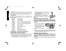
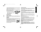
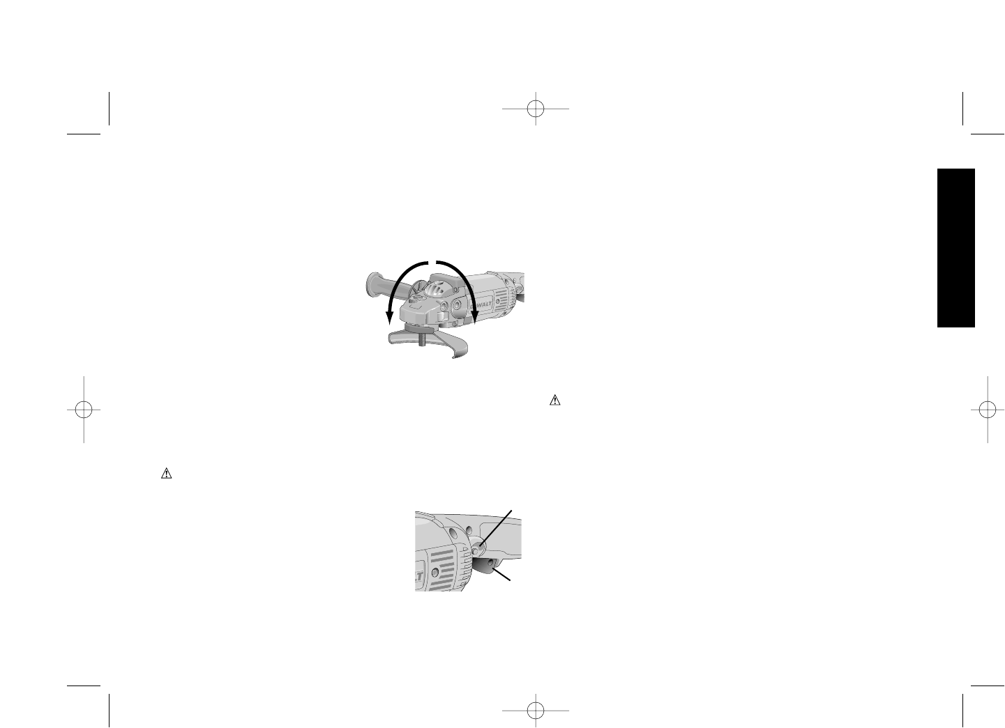
2. Without separating the gear case from motor housing, rotate the
gear case head to desired position.
NOTE: If the gear case and motor housing become separated by
more than 1/8", the tool must be serviced and re-assembled by a
D
EWALT service center. Failure to
have the tool serviced may cause
brush, motor and bearing failure.
3. Re-install screws to attach the
gear case to the motor housing.
Tighten screws to 20 in lbs
torque. Overtightening could
cause screws to strip.
OPERATION
Power Source
Plug the Large Angle Grinder into a dedicated electrical circuit.
Operating this tool on a circuit with other tools will decrease tool
performance.
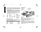
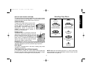
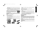
Switch
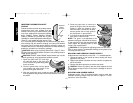
CAUTION: Before connecting the tool to a power source or after
a power failure, depress and release the trigger switch (A) once
without depressing the lock-on button (B) to
ensure that the switch is in the off position. If
the trigger switch is locked on, the tool will
start unexpectedly when power is reconnect-
ed to the tool. Hold the side handle and rear
handle firmly to maintain control of tool at
start up and during use.
TRIGGER OPERATION
To turn the tool on, depress the trigger switch (A). The tool will
remain running while the trigger is depressed. Turn the tool off by
releasing the trigger.
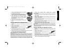
TRIGGER OPERATION WITH LOCK-ON FEATURE
To turn tool on, depress trigger. Depress and hold lock-on button
(B) while releasing trigger. Lock-on button will remain depressed
and tool will remain on.
To turn the tool off, depress and release trigger.The lock pin button
will pop out, permitting the trigger to disengage and causing the tool
to turn off.
NOTE: Allow the tool to reach full speed before touching tool to
work surface. Lift the tool from the work surface before turning the
tool off.
CAUTION: Make sure the wheel has come to a complete stop
before setting the tool down.
REMOVAL OF LOCK-ON FEATURE
The lock-on button can be permanently removed without compro-
mising compliance with regulatory agencies shown on the tool’s
nameplate. Removal of the lock pin must be done by a D
EWALT
Service Center.
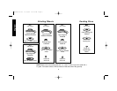
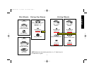
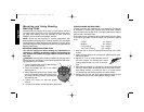
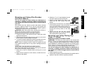
Mounting and Using Depressed Center
Grinding Wheels and Sanding Flap
Discs
MOUNTING AND REMOVING GUARD
Turn off and unplug tool before making any adjustments or
removing or installing accessories. Before reconnecting the
tool, depress and release the trigger switch to ensure that the
tool is off.
90˚
90˚
A
B
399080-02 rev 11/15/02 10:13 AM Page 9