


English
8
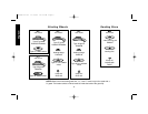
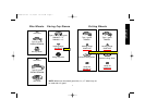
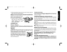
• Two rear positions: Rear handle positions
are designed for optimized balance in edge
grinding applications.
• One top position: Top handle position is
designed for edge grinding applications.
NOTE: D28497 includes only three handle
positions.
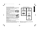
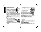
Rotating the Rear Handle
Turn off and unplug tool before making any adjustments or
removing or installing accessories. Before reconnecting the
tool, depress and release the trigger switch to ensure that the
tool is off.
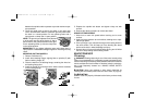
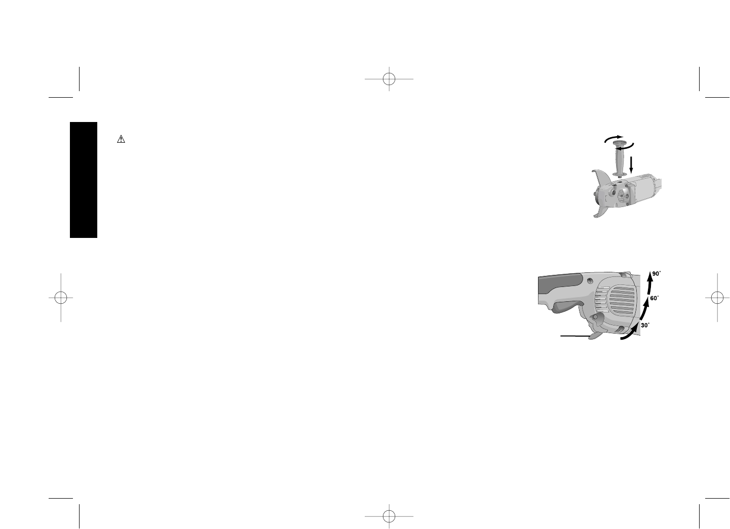
1. Unlock the rear handle by
pulling out the Handle Re-
lease Lever (G) as shown.
2. Rotate handle into available
0°, 30°, 60°, or 90° position
left OR right of center.
3. Push in the handle release
lever.
4. Before turning the tool on, ensure that the handle is locked into
a position and the handle release lever has returned to the orig-
inal position flush with the tool housing.
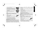
Rotating the Gear Case
Turn off and unplug tool before making any adjustments or
removing or installing accessories. Before reconnecting the
tool, depress and release the trigger switch to ensure that the
tool is off.
1. Remove the four corner screws attaching the gear case to motor
housing.
CAUTION: Accessories must be rated for at least the speed
recommended on the tool warning label. Wheels and other acces-
sories running over rated speed can fly apart and cause injury.
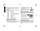
ATTACHMENTS
Attachments designed specifically for this grinder can be
purchased through D
EWALT dealers and DEWALT Factory
Service centers.
D284939 9" Type 27 guard
D284948 9" Type 28 guard
D284937 7" Type 27 guard
D284936 6" Type 11 Flaring cup guard with flange
D284934 4" Type 11 Flaring cup guard with flange
D284933 Type 11 flaring cup wheel backing flange
D284932 Type 1 Flange set
D284931 7" Type 1 Guard
054339-00 Grinding backing flange
22191-00 Clamp nut
61820-01 Wheel Wrench
445928-01 Soft mount spindle protector
397711-00 Rubber gear case bumper
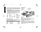
ASSEMBLY AND ADJUSTMENTS
Attaching the Side Handle
To install the side handle, thread the handle into one of the five
positions listed below and tighten securely by turning clockwise.
• Two front positions: Forward handle positions are designed for
optimized balance in surface finishing applications.
G
399080-02 rev 11/15/02 10:13 AM Page 8