


30
.
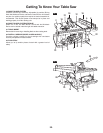
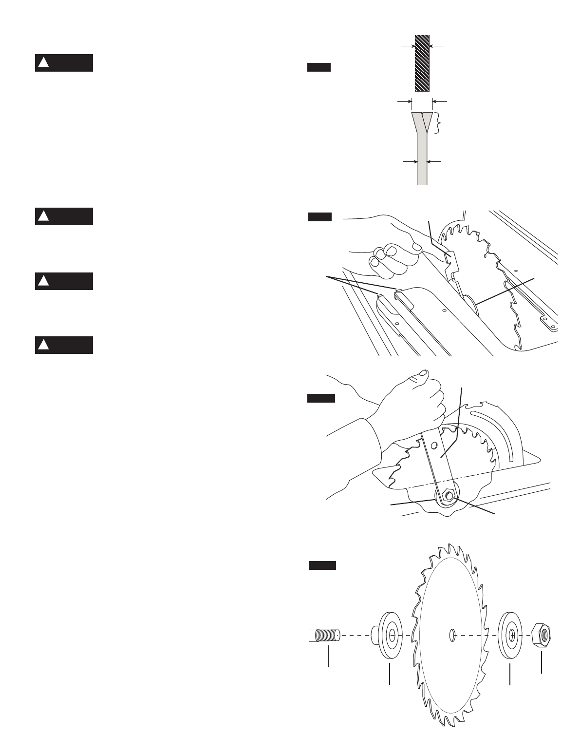
Changing The Blade
To prevent personal injury, always discon-
nect plug from power source before chang-
i
ng blades.
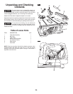
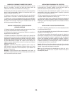
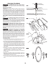
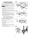
Using the Correct Blade
IMPORTANT:
The saw blade provided on this tool has a
carbide-tipped kerf width of .128” and a plate (body) thickness
t
hat is .086” thick. When looking for a replacement blade, select
one with dimensions close to the original blade. This information
may not be printed on the blades packaging. If not, check the
m
anufacturers catalog or website. Bosch offers an extensive line
of Premium-Quality Professional Saw Blades that match the
requirements for this tool. You must select a blade with a kerf
w
idth of .092” or more and a plate (body) thickness .088” or less
(Fig. 10).
To reduce the risk of injury, do not use extra
thin kerf saw blades.
The kerf of the blade
must be wider than .092”. Extra thin kerf saw blades (less than
.092”) may cause the work piece to bind against the riving knife
during cutting. It is recommended that the kerf of the
replacement blade used on this saw be .092” or more.
To reduce the risk of injury, do not use saw
blades made with a thick body plate.
If the
replacement saw blade's plate thickness is greater than .088”,
the riving knife would not properly serve as an aid to reduce
kickback. The replacement blade's plate thickness must be less
than .088”.
To reduce the risk of injury, do not use blade
“dampeners,” “stabilizers,” or “stiffening
collars” on both sides of a replacement blade.
These are
metal plates positioned against the sides of the blade to reduce
deflection that may occur when using thin saw blades. Use of
these devices on both sides will prevent the blade from being
properly aligned with the riving knife, which may bind the work
piece during cutting. One “stabilizer” plate may be placed only
against the outside of a thin replacement blade. These plates are
not required with the supplied Bosch blade.
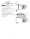
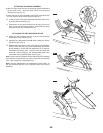
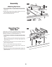
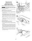
Changing the Blade
1. Turn elevation wheel clockwise until the blade is up as high as
it will go, remove table insert
1 using finger hole (Fig. 11).
2.
Lift up arbor lock lever
2 and slowly rotate blade by hand until
lock fully engages saw arbor and stops rotation (Fig. 11).
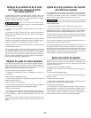
Loosen arbor nut
3 counter clockwise with the arbor wrench 4
provided (Fig. 12). Set wrench aside and continue to loosen
arbor nut
3 by hand and remove arbor nut 3 and outer washer
5. Blade may now be removed or installed by sliding on or off
arbor shaft
6.
3. Assemble inner washer
7 and new blade as shown in figure
13, making certain the TEETH OF THE BLADE ARE
POINTING DOWN AT THE FRONT OF THE TABLE.
NOTE: The printing on different saw blades are not always on
the same side.
4.
Assemble outer washer
5, arbor nut 3 as shown in figure 13.
While lifting up arbor lock lever
2 securely tighten arbor nut 3
clockwise with the wrench 4. (Fig. 12).
5. Position table insert in pocket of table so tabs
8 on table insert
1 are in slots in pocket of table and push down and secure in
place.
B
LADE BODY PLATE
P
LAQUE DU CORPS DE LA LAME
PLACA DEL CUERPO DE LA HOJA
MUST BE .088” OR LESS
DOIT ÊTRE DE 0,088 PO OU MOINS
DEBE SER 0.088 PULGADAS O MENOS
KERF WIDTH
LARGEUR DE VOIE
ANCHURA DE LA SECCIÓN DE CORTE
RIVING KNIFE
COUTEAU DIVISEUR
CUCHILLA SEPARADORA
M
UST BE .092” OR MORE
D
OIT ÊTRE DE 0,092 PO OU PLUS
DEBE SER 0.092 PULGADAS O MÁS
.
090”
BLADE TEETH
DENTS DE LA SCIE
DIENTES DE LA HOJA
FIG. 12
FIG. 13
2
7
1
FIG. 11
FIG. 10
8
3
4
5
W
ARNING
!
WARNING
!
WARNING
!
WARNING
!
3
5
7
6