


46.
reverse, the guard can be easily removed for special operations
s
uch as dados or rabbets.
T
he Anti-Kickback Device can be easily attached by aligning the
attachment pin with the hole in the rear of the riving knife. It can
be easily removed by depressing the compression pads on
e
ither side of the Anti-Kickback Device and lifting it away.
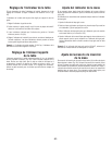
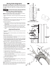
The Riving Knife can be easily adjusted to one of three heights
by removing the table insert, raising the blade to its full height
and releasing the riving knife release lever at the base of the
Riving Knife. The Riving Knife should be locked in its highest
position for use with the Main Barrier Guard and Anti-Kickback
Device. It can be adjusted to its middle position for non-through
cuts and for use as a material splitter without the Main Barrier
Guard and Anti-Kickback Device.
In the event that the Riving Knife can not be used for a specific
cut, it can be adjusted to its lowest position, thus placing it 1”
above the surface of the table (while the blade is at its full
height).
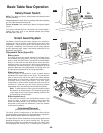
System Storage
When not in use, the Main Barrier Guard and Anti-Kickback
Device can be stored under the right side table extension.
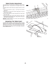
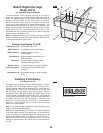
Use of all the components of the Smart Guard
System, including Main Barrier Guard, Anti-
Kickback Device, and Riving Knife is highly recommended to
provide protection against accidents and injury.
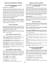
1. Slide the Main Barrier Guard assembly (upside down) up and
back into the U-bracket at the rear right side of the saw (Fig. 33).
2. Pivot the rear of the guard up and into the front mounting
bracket.
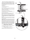
3. Lock the Main Barrier Guard assembly into place in the same
manner as you would attach it to the Riving Knife (Fig. 34).
4. Attach the Anti-Kickback Device to the hanging bracket in the
same manner that it attaches to the Riving Knife.
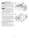
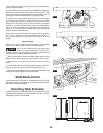
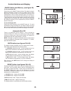
Blade Bevel Control
Loosen blade bevel lock handle 1 counterclockwise (Fig. 35), slide
the elevation wheel
2 until pointer 3 is at desired angle and tighten
blade tilt lock handle
1 clockwise.
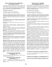
Extending Table Extension
To extend the table, raise the table extension lock handle 4 (Fig. 35)
and slide table extension
5 to desired width (Fig 36). To secure
table setting, lower the lock handle
4.
1
2
3
4
FIG. 33
F
IG. 34
FIG. 35
FIG. 36
WARNING
!
4
2
1
3
5