


FPE-1000-SLC en 7
Bosch Security Systems, Inc. F.01U.078.099 | 5.0 | 2011.11
Observe maximum circuit resistance of 50 Ω.
For Class B, the total wire length of all branches connected to one
FPE-1000-SLC module (terminals S1+/SC1- and S2+/SC2-) must not exceed
30,000 feet (9140 m).
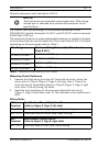
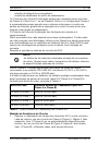
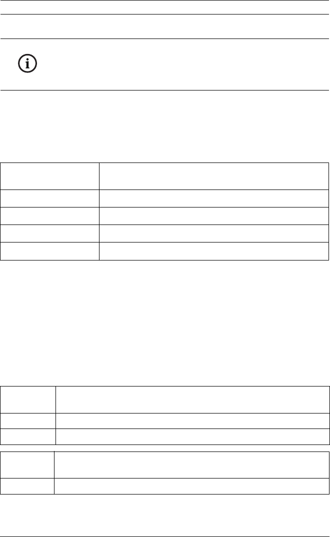
The maximum distance an analog addressable detector or module is allowed
to be located from the control panel (for Class A and Class B SLC) is limited
depending on the wire gauge; refer to Table 1.
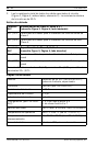
Table 1 Maximum Wiring Distance for SLC Circuits
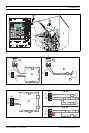
Measuring Circuit Resistance
1. Remove the field wiring from the SLC terminals and short either the
return wire in Class A (Figure 2, Page 4, left side, Item 1 Class A) or
short the end of the farthest device in Class B (Figure 2, Page 4, right
side, Item 1 Class B) using clip leads.
2. Read the total resistance of all wires associated with the circuit
(Figure 2, Page 4, both sides, item 2). The maximum circuit resistance is
50 Ω.
Wiring Styles
NOTICE!
Wire distances are computed using copper wire. When using
twisted pair or sheilded wire, observe the maximum circuit
specifications.
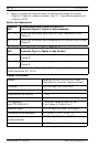
Wire Gauge Maximum Wiring Distance (for Class A and
Class B SLC)
12 AWG (3.3 mm
2
)
10,000 feet (3050 m)
14 AWG (2.1 mm
2
)
10,000 feet (3050 m)
16 AWG (1.3 mm
2
)
6200 feet (1890 m)
18 AWG (0.8 mm
2
)
3900 feet (1190 m)
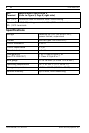
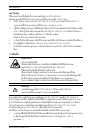
SLC
Terminal
Specification Class A Style 6 and 7
(refer to Figure 3, Page 4, left side)
S1+ | SC1- Terminals used for outgoing loop Class A wiring
S2+ | SC2- Terminals used for return loop Class A wiring
SLC
Terminal
Specification Class B Style 4
(refer to Figure 3, Page 4, right side)
S1+ | SC1- Terminals used for first stub Class B wiring