


CHUCK KEY & STORAGE AREA
Your tool is equipped with a chuck key that is
conveniently located on the cord protector
where it is always handy and unlikely to get lost
or misplaced (Fig. 1).
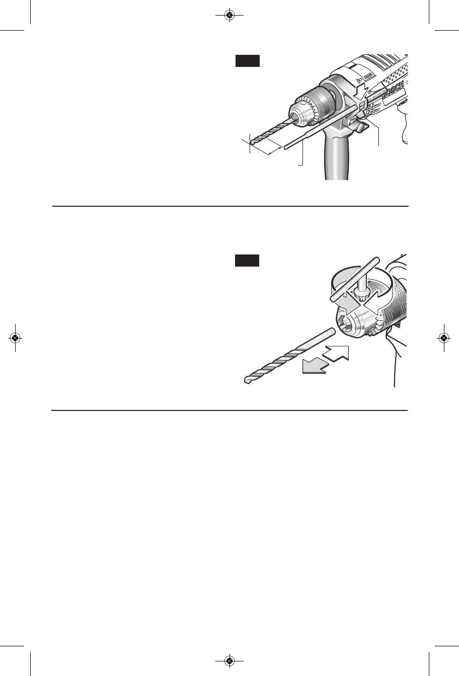
INSERTING BIT
For small bits, open jaws enough to insert the
bit up to the flutes. For large bits, insert the bit
as far as it will go. Center the bit as you close
the jaws by hand. This positions the bit
properly, giving maximum contact between the
chuck jaws and the bit shank.
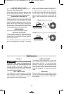
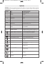
To tighten chuck, insert key into each of the
three key holes in succession and tighten
clockwise firmly. The chuck can be released by
using one hole only (Fig. 6).
-9-
Operating Tips
You will extend the life of your bits and do
neater work if you always put the bit in contact
with the work before pulling the trigger. During
the oper a tion, hold the tool firmly and exert
light, steady pressure. Too much pressure at
low speed will stall the tool. Too little pressure
will keep the bit from cutting and cause excess
friction by sliding over the surface. This can be
damaging to both tool and bit.
DRILLING WITH VARIABLE SPEED
The trigger controlled variable speed feature
will eliminate the need for center punches in
hard materials. The variable speed trigger
allows you to slowly increase RPM. By using a
slow starting speed, you are able to keep the bit
from “wander ing”. You can increase the speed
as the bit “bites” into the work by squeezing the
trigger.
DRIVING WITH VARIABLE SPEED
Variable speed drills will double as a power
screwdriver by using a screwdriver bit in the drill
mode. The technique is to start slowly,
increasing the speed as the screw runs down.
Set the screw snug ly by slowing to a stop. Prior
to driving screws, pilot and clearance holes
should be drilled.
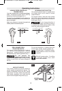
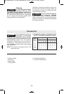
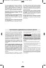
DEPTH GAUGE
Your drilling depth can be pre-set and/or
repeated by using the depth gauge.
Setting depth: After the auxiliary handle is
installed, make sure the accessory has been
fully inserted into the tool holder before setting
the depth gauge (Fig. 5).
To adjust depth, push down on the depth
gauge release lever, slide the depth gauge to
desired depth and release pressure on lever to
lock the depth gauge in place (Fig. 5).
x
DEPTH GAUGE
DEPTH GAUGE
RELEASE
LEVER
FIG. 5
Counter
Clockwise
Clockwise
FIG. 6
BM 160992A08A 01-13_BM 160992A08A 01-13.qxp 1/10/13 2:44 PM Page 9