


-25-
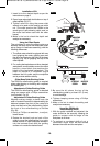
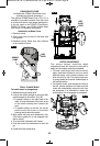
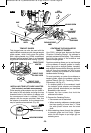
TEMPLET GUIDES
This plunge base can also be used with the
optional Bosch-exclusive quick-change templet
guide system, which firmly grips the guides
with a spring-loaded ring. Unlike conventional
threaded templet guides, there is no threaded
ring that can come loose while routing. (Fig. 45)
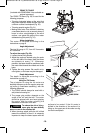
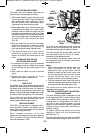
INSTALLING TEMPLET GUIDE ADAPTER
(Not included, available as accessory)
Place templet guide adapter over the holes in
the center of the sub-base, and align the two
threaded holes in the bottom of adapter with
the countersunk holes in subbase. Fasten
adapter with the screws provided. Note that
the adapter is reversible, so the release lever
may be positioned as desired. (Fig. 46)
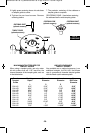
CENTERING THE SUB-BASE OR
TEMPLET GUIDES
Your PR011 plunge base features the Bosch
“Precision Centering Design”. Its subbase is
precisely centered at the factory. This positions
the bit at the center of the subbase and
optional templet guides.
Precision centering allows you to use the edge
of the subbase or templet guides to closely
follow jigs such as straight guides, templets,
and dovetail fixtures without worrying about bit
walk-off from the intended cut line for any
reason, including the orientation of the router’s
handles relative to the jig.
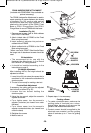
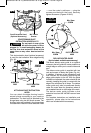
To most precisely re-center the subbase or
templet guides, attach the subbase using the
optional Bosch RA1151 Centering Device.
Follow steps 1-8 (Fig. 47).
1. If a templet guide is to be centered, Install
the templet guide adapter and template
guide (optional attachments) as described
elsewhere in this manual.
2. Loosen the four screws that hold the
subbase to the base.
3. Prepare the Centering Device:
• Use narrow end of steel shaft.
• When centering subbase or templet guide
that has opening of more than ½”, slide
the wide plastic sleeve over the steel
shaft.
4. Slide centering sleeve through the subbase
or templet guide and into collet. Tighten
collet nut with fingers to put slight grip on
centering cone.
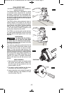
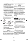
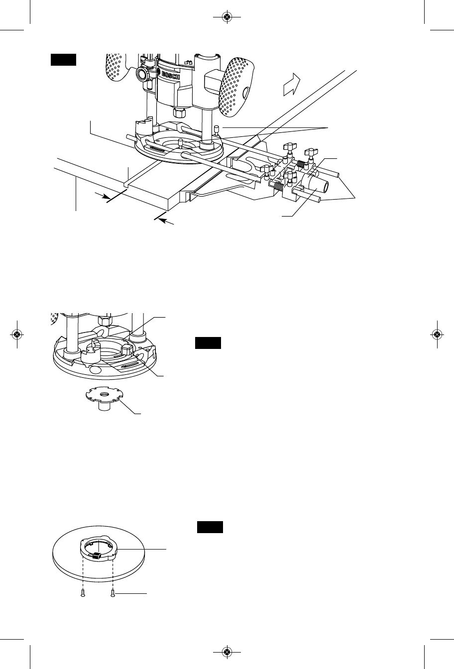
BASE
CUT
DESIRED
WIDTH
M6 WING SCREW
ROUTER
GUIDE RODS
FINE ADJUSTMENT
KNOB
FINE
ADJUSTMENT
INDICATOR
WORKPIECE
FEED
DIRECTION
FIG. 44
TEMPLET GUIDE
ADAPTER
(optional accessory)
MOUNTING SCREWS
FIG. 46
TEMPLET GUIDE
ADAPTER
TEMPLET GUIDE
RELEASE LEVER
TEMPLET GUIDE
(optional accessory)
FIG. 45
BM 2610021461 06-12_BM 2610021461 06-12.qxp 6/26/12 1:38 PM Page 25