


Page 1
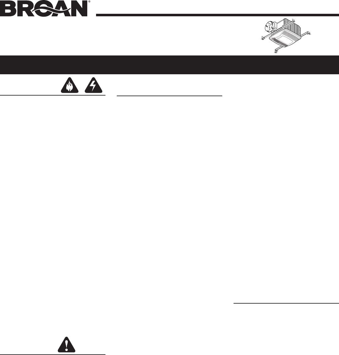
MODEL QTXE110SFLT
WARNING
TO REDUCE THE RISK OF FIRE, ELECTRIC
SHOCK, OR INJURY TO PERSONS, OB-
SERVE THE FOLLOWING:
1. Use this unit only in the manner intended
by the manufacturer. If you have questions,
contact the manufacturer at the address or
telephone number listed in the warranty.
2. Before servicing or cleaning unit, switch
power off at service panel and lock the ser-
vice disconnecting means to prevent power
from being switched on accidentally. When
the service disconnecting means cannot be
locked, securely fasten a prominent warning
device, such as a tag, to the service panel.
3. Installation work and electrical wiring must be
done by a qualied person(s) in accordance
with all applicable codes and standards,
including re-rated construction codes and
standards.
4. Sufcient air is needed for proper combustion
and exhausting of gases through the ue
(chimney) of fuel burning equipment to pre-
vent backdrafting. Follow the heating equip-
ment manufacturer’s guideline and safety
standards such as those published by the
National Fire Protection Association (NFPA),
and the American Society for Heating, Re-
frigeration and Air Conditioning Engineers
(ASHRAE), and the local code authorities.
5. When cutting or drilling into wall or ceiling, do
not damage electrical wiring and other hidden
utilities.
6. Ducted fans must always be vented to the
outdoors.
7. Acceptable for use over a tub or shower when
connected to a GFCI (Ground Fault Circuit
Interrupter) - protected branch circuit.
8. This unit must be grounded.
CAUTION
1. For general ventilating use only. Do not use
to exhaust hazardous or explosive materials
and vapors.
2. This product is designed for installation in
at ceilings only. DO NOT MOUNT THIS
PRODUCT IN A WALL.
3. To avoid motor bearing damage and noisy
and/or unbalanced impellers, keep drywall
spray, construction dust, etc. off power unit.
4. Please read specication label on product for
further information and requirements.
HUMIDITY SENSING
FAN / FLUORESCENT LIGHT / NIGHT LIGHT
READ AND SAVE THESE INSTRUCTIONS
CLEANING &
MAINTENANCE
Installer: Leave this manual
with the homeowner.
For quiet and efcient operation, long life,
and attractive appearance - lower or remove
grille and vacuum interior of unit with the
dusting brush attachment.
The motor is permanently lubricated and
never needs oiling. If the motor bearings are
making excessive or unusual noises, replace
the motor with the exact service motor. The
impeller should also be replaced.
SENSOR CLEANING
The humidity sensor is mounted in the grille.
The sensor will operate most reliably when
cleaned occasionally as follows:
1. Disconnect power at service entrance.
2. Remove the grille. Use a dry dustcloth,
clean toothbrush, or lightly vacuum to
clean sensor and grille. DO NOT USE
ABRASIVE CLOTH, STEEL WOOL
PADS, OR SCOURING POWDERS.
3. DO NOT USE cleaning sprays, solvents,
or water on or near the sensor!
OPERATION
To register this product visit:
www.broan.com
The humidity control and fan can be
oper-ated separately. Use a 1- or 2-func-
tion wall control. Do not use a dimmer
switch to operate the humidity control or
light. See “Connect Wiring” for details.
SENSOR OPERATION
This humidity-sensing
fan responds to:
(a) rapid to moderate humidity increases
and (b) humidity above a 50%-100% rela-
tive humidity set-point. (a) and (b) are set
with “SENSITIVITY” adjustment. Fan may
occasionally turn on when environ-mental
conditions change. If the fan contin-uously
responds to changing environ-mental condi-
tions, “SENSITIVITY” adjust-ment may be
required (see section below).
STATUS INDICATOR
This indicator can only be seen by looking
directly at it. Normal mode is 5-seconds on
and off. If it blinks rapidly for 5-seconds and
then off, check sensor connections on grille
and fan housing.
MANUAL ON WITH TIMED OFF
For odor or vapor control, the fan can be en-
ergized by cycling its wall-mounted switch
if one is installed. Once the fan has been
turned on in this manner, it will remain on
for the set “TIMER” period.
To manually energize the fan:
1. Go to Step 2 if switch is already on;
otherwise, turn switch on for more than
1 second.
2. Switch off for less than 1 second.
3. Switch back on and fan will turn on.
SENSITIVITY ADJUSTMENT
“SENSITIVITY” has been factory set for
most shower applications. If the fan is in a
tub area or is used for dampness control,
the “SENSITIVITY” may need to be in-
creased toward maximum (“MAX.”). If the
control is responding too often to changing
environmental conditions, adjustment to-
ward less (“MIN.”) “SENSITIVITY” may be
required. To adjust the “SENSITIVITY”:
1. Turn power off at electrical service
panel.
2. Through the grille, locate the
“SENSITIVITY” screwdriver slot.
3. Using a small, at-blade screwdriver,
carefully rotate “SENSITIVITY” adjust-
ment toward “MAX.” or “MIN.”
4. Turn power on and check operation
by turning on shower or other humidity
source until fan turns on.
5. Repeat above steps if necessary.
TIMER ADJUSTMENT
This humidity-sensing fan has a “TIMER”. It
is user-adjustable from 5 to 60 minutes and
is factory-set at 20 minutes. The “TIMER”
controls how long the fan remains on (a)
after rise in humidity and (b) humidity level
are both below the user-adjustable “SEN-
SITIVITY” setting or after being energized
by cycling power switch.
To adjust the “TIMER”:
1. Disconnect power at electrical service
panel.
2. Through the grille, locate the “TIMER”
screwdriver slot.
3. Using a small, at-blade screwdriver,
carefully rotate “TIMER” adjustment to
desired setting (5 to 60 minutes).
4. Check operation by cycling power
switch as instructed under “MANUAL
ON WITH TIMED OFF” or by turning on
a humidity source until fan turns on.
5. Check “TIMER” setting with watch or
clock after turning humidity source off
if it was turned on it Step 4.
6. Repeat above steps if necessary.