CONTROL WIRING
BATTERY BACKUP
If the gate operator is already factory equipped with battery
run, only the Right/Left Side switch and Mode 1 are supported
(Figure 3). The Right/Left switch must to be set in the same
position as the Right/Left switch on the main control board.
(See page 22 for correctly setting the Right/Left switch on the
control board.) Gate will continue to operate when power is lost.
• NOTE: Mode 2 operation is no longer supported.
INSTALLATION
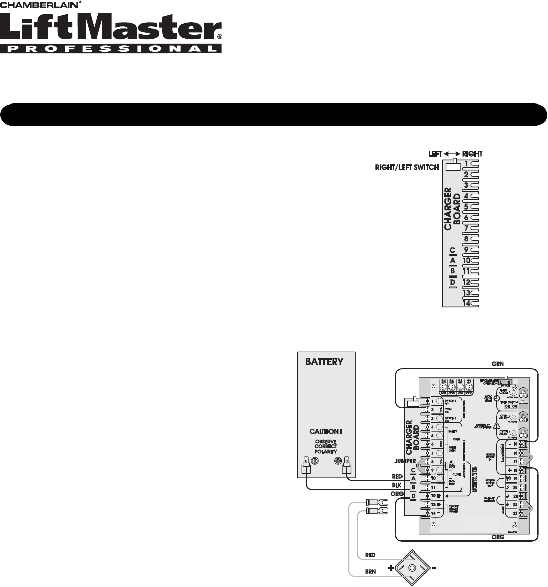
If the gate operator did not come from the factory equipped with
battery run, field installation of battery run is very simple. The
illustration at right shows additional wiring required for battery
run that is not part of the standard wiring (Figure 4).
1. Disconnect power to gate operator.
2. Disconnect the brown and red wires from terminals 13 and
14 and insulate the ends of the wires.
3. Secure the charger board to the main control board by
attaching to the 14 screw terminal on the left side of the
control board.
4. Connect a green wire from terminal 2 to terminal 15 of the
control board.
5. Attach an orange wire from terminal D of the charger board
to terminal 18 of the main control board.
6. Attach a red wire from terminal A to battery positive and a
black wire from terminal B to battery negative.
Figure 3
Figure 4
Disconnect these
existing wires
from 13 and 14.
(Set same as RIGHT/LEFT
switch on control board.)
Existing
Bridge
Rectifier
WIRING
This addendum is to be used in conjunction with the owner’s manual. Refer to the manual for all mounting and
wiring instructions with the exception of page 14. For page 14, follow instructions shown below.
© 2008, The Chamberlain Group, Inc.
01-34563 All Rights Reserved
Addendum For
SL930


