


Page 11For technical questions, please call 1-888-866-5797.Item 69078
Operating Instructions
Read the ENTIRE IMPORTANT SAFETY INFORMATION section at the beginning of this
manual including all text under subheadings therein before set up or use of this product.
Tool Set Up
TO PREVENT SERIOUS INJURY FROM
ACCIDENTAL OPERATION:
Release the Trigger, turn off the laser and
unplug the tool from its electrical outlet before
adjusting tool or installing accessories.
TO PREVENT SERIOUS INJURY
FROM FLYING FRAGMENTS:
Do not use blades made from high-speed steel,
abrasive blades, or metal- or masonry-cutting blades.
The guards of this saw are not designed to
protect against the failure of such blades.
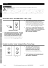
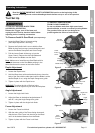
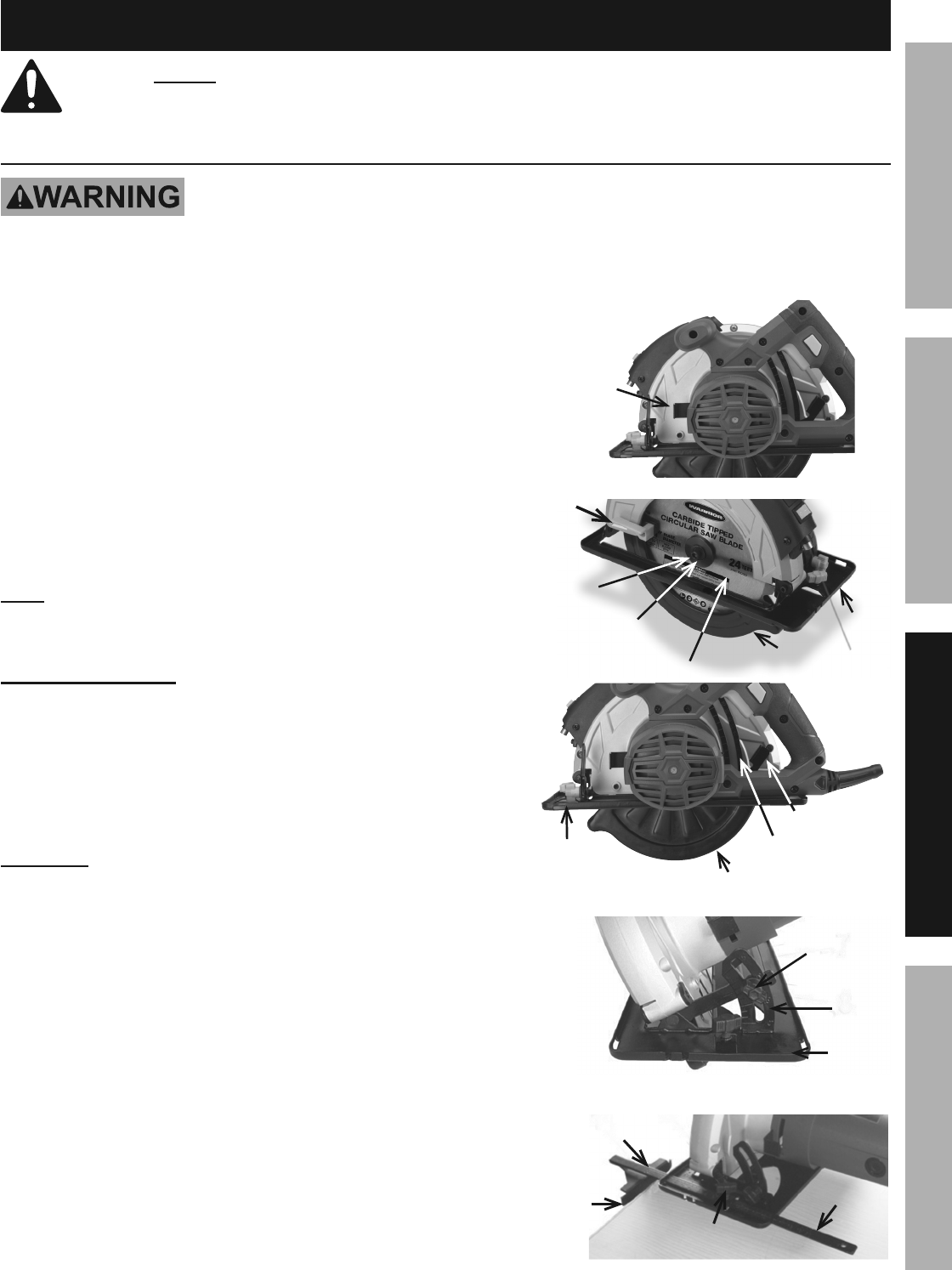
To Remove/Install A Saw Blade (sold separately):
1. Lower the Base Plate to its lowest setting
(See Depth Adjustment, following).
2. Depress the Spindle Lock Lever to hold the Saw
Blade in place and unscrew (counterclockwise) and
remove the Blade Clamp Bolt and Outer Flange.
3. Pull the Lower Guard all the way up into the
Upper Guard. Remove the old Saw Blade and
install a new Saw Blade onto the Shaft.
Note: Make sure to install the new Saw Blade with its
teeth and the arrow on the Saw Blade pointing in the
same direction as the arrow on the Lower Guard.
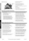
Depth Adjustment
1. Loosen the Depth Lever.
2. Hold the Base down with one hand and raise or lower the
body of the Saw with the other hand until the Blade is at the
desired Depth of cut, using the Depth Gauge as a guide.
3. Tighten in place with the Depth Lever.
WARNING! To reduce the risk of Serious Injury:
Depth of cut must be adjusted to just clear the workpiece.
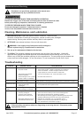
Angle Adjustment
1. Loosen the Angle Lock Knob.
2. Adjust the Base to the desired angle between 0°
and 45°, using the Angle Gauge as a guide.
3. Tighten in place with the Angle Lock Knob.
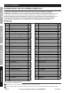
Fence Adjustment
1. Loosen the Fence Lock Knob.
2. With the main guide of the Fence facing downward,
slide the bar of the Fence into the slots on the Base
until it is the desired distance from the Blade.
3. Tighten in place with the Fence Lock Knob.
Figure 2
Spindle
Lock Lever
Base
Lower Guard
Outer
Flange
Blade Clamp Bolt
Saw Blade
Lower
Guard
Lever
Figure 3
Lower Guard
Base
Depth Gauge
Depth Lever
Figure 4
Angle Lock
Knob
Base
Angle
Gauge
Figure 5
Fence
Bar of Fence
Fence Lock
Knob
Main
guide of
Fence
SAFETYOPERATIONMAINTENANCE SETUP