


Installation Instructions for UEL Emergency
Self Diagnostic Lighting Fixtures
IMPORTANT SAFEGUARDS
WHEN USING ELECTRICAL EQUIPMENT, BASIC SAFETY PRECAUTIONS SHOULD ALWAYS
BE OBSERVED INCLUDING THE FOLLOWING:
1. READ AND FOLLOW ALL SAFETY INSTRUCTIONS
2. Do not mount near gas or electric heaters.
3. Equipment should be mounted in locations and at heights where it will not readily be subjected to tampering by unauthorized
personnel.
4. Do not use this equipment for other than its intended purpose.
5. To be completed by a qualified electrician only.
6. Disconnect power supply before servicing fixture.
7.
SAVE THESE INSTRUCTIONS
INST
ALLATION
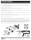
Step 1. Turn off AC Power
Step 2. Access backplate for mounting by removing the four screws holding the clear weather shield, and the two screws retaining the plastic cover.
NOTE: Due to the airtight nature of the UEL, the shield may be held on by a slight vacuum. If this occurs, carefully pry the corners of the shield up
using a flat head screwdriver.
Step 3. For some mountings, it may be necessary to remove the battery. Do this by first unplugging the battery from the printed circuit board. Then, unfasten the
hook and loop strap from the battery, and remove the battery.
NOTE: When mounting the UEL, it is important to consider the weight of the unit, thirteen pounds. A suitable anchor is recommended, or mounting directly
to a stud, for the unit itself, or the junction box the unit is mounted to.
Step 4. For rear mounting drill or knock out center hole and required screw locations for junction box. Bring wires through center hole, and attach mounting plate to
junction box. For conduit mounting, drill or knock out 7/8” diameter conduit holes. Conduit knockout holes are on the top surface of the back plate. Attach
conduit fittings, making sure to use 1/2” liquid tight fittings if the unit required to be sealed against moisture.
NOTE: When back mounting the UEL on an uneven surface such as brick or stucco, silicone caulk should be used to prevent water from seeping in between the
unit and the J-box.
Step 5. Connect power supply in accordance with local codes. Wire connections as follows: 277V line to Orange lead; 120V line to Black lead; Neutral to White
lead. Cap unused line lead. (See Wiring Diagram) Insert the supply wires (strip length 3/8") into the appropriate push in connector on the transformer leads;
see wiring diagram for details.
Step 6. Once the AC wiring is completed, if necessary, reinstall the battery.
Step 7. Replace the cover and reinstall the cover mounting screws.
COOPER LIGHTING
Customer First Center 1121 Highway 74 South Peachtree City, GA 30269 7/23/07 049-180 RevE
WARNING
Risk of Fire/Electric Shock.
If not qualified, consult an
electrician.
MISE EN GARDE
Risque d'incendie/de choc électrique.
Contacter un électricien si vous n'êtes
pas qualifié.
PRECAUCION
Riesgo de Incendio/Desarga Electrica.
Si no esta calificado, consulte a un
electricista.
NEMA type 4X rated enclosure: Raintight, Watertight, and Corrosion Resistant
Suitable for Wet Locations, For use in –35°C (-31°F) to 50°C (122°F) ambient environments.
NSF- Splash Zone Certified
MR16 lamps, 24W (combined) Maximum.