


assembly
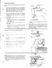
9.
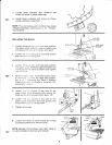
Loosen the
two
screws
that
secure
the
lower
blade
guides
and separate
them
about
1/8".
10.
Loosen
the screw holding the
lower blade
guide
support
and slide support all the
way
toward
the
rear of the saw,
and
retighten
all
screws.
WARNING:
TO AVOID BEING SCRAPED
SHOULD BLADE SUDDENLY
UNCOIL,
WEAR
SAFETY GOGGLES
AND
CAREFULLY
UNCOIL
THE BLADE
HOLDING IT AT ARMS LENGTH.
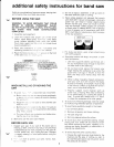
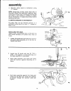
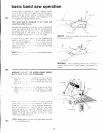
11. Place
the
blade over
the
wheels
with the
teeth
pointing
downward toward
the table
as
shown.
Make sure the
blade is
in
the
center
of the
rubber
tires.
NOTE:
Your bandsaw can
use
1/8 or
114
inch
wide
blades, 56-718
inches long.
A l14inch blade
is included
with this saw.
ry
:.
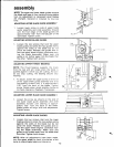
IENSION WHEEL
SIOT
IN TABLE
DRIVE
V/IEEt
DLER
WHEET
TENSIONING
THE
BLADE
The bandsaw
is equipped
with
a self-limiting
tension
device.
The
tension
is
factory
set
and
should
not
need adjustment.
The blade
must
be
installed
before tension
can
be set.
1. Turn tension
adjustment
knob
until
knob
contacts
washer and
sleeve.
2. DO NOT turn
knob after
contact
is
made
and
resistance
if
felt.
This
is
the
proper
tension
setting
tor a114"
blade.
3.
To release tension
turn
knob
counterclock-
wise until
knob is above
the
washer and
sleeve.
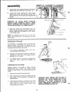
COMPENSATION
FOR WEAR
Tension
screw
is
provided
to
make
minimal
adjustments
due to
wear. The tension
screw
creates
a drag
between the
wheel
guide
and the
frame.
1. Remove the
blade
before
adiusting.
2.
Use a
phillips
screw
driver to
adjust
the ten'
sion
screw.
Turn clockwise
to
increase the
drag
(tension).
3. Check
tension
by
lifting up on
tension
knob.
lf the
tension
knob will
not move
the
tension screw
is too
tight.
Adjust by
turntng
tension
screw
coun-
terclockwise
and
recheck,
WARNING:
OVER
TENSION
AND
FAILURE
TO
PROPERLY
SET
BLADE
GUIDES
AND
THRUST
BEARING
WILL
CAUSE
PREMATURE
BLADE
BREAKAGE.
FOLLOW
ADJUSTING
BLADE
GUIDE
ASSEMBLIES
COMPLETELY
TO
HELP
MAINTAIN
NORMAL
BLADE
LIFE.
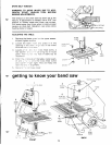
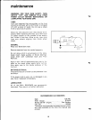
TENSION SCREW
10
Q