


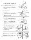
assembly
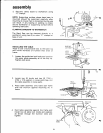
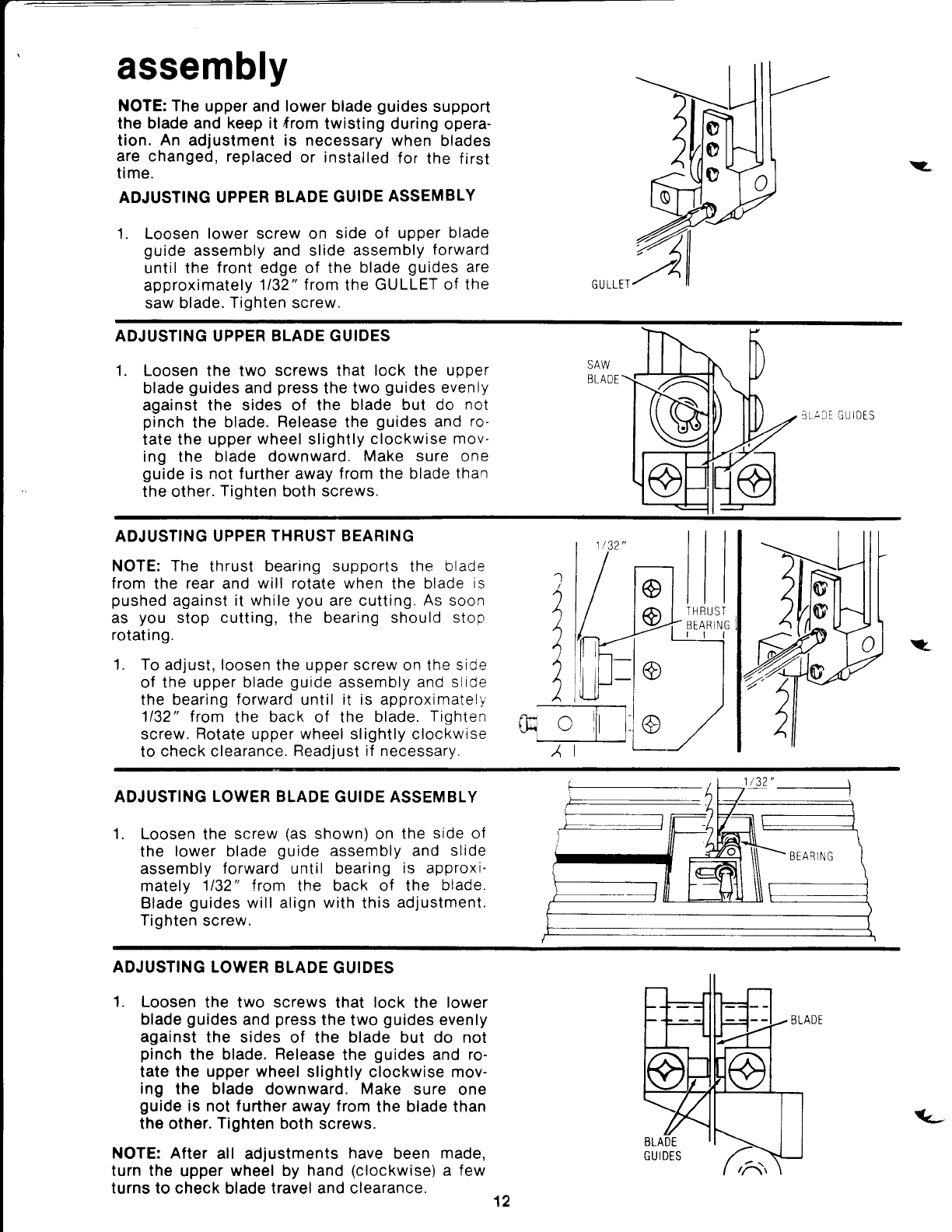
NOTE: The
upper and lower
blade
guides
support
the blade and
keep
it
from
twisting during
opera-
tion.
An
adjustment is necessary when
blades
are changed,
replaced
or installed
for
the
first
time.
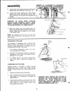
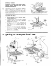
ADJUSTING UPPER
BLADE
GUIDE
ASSEMBLY
1.
Loosen
lower screw on
side
of
upper
blade
guide
assembly and slide
assembly
forward
until the
front
edge of the
blade
guides
are
approximately
1/32" from
the
GULLET
of the
saw blade.
Tighten
screw.
:.
GULLEI
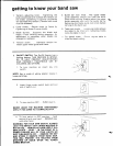
ADJUSTING UPPER BLADE GUIDES
1. Loosen
the two
screws
that
lock
the
upper
blade
guides
and
press
the two
guides
evenly
against the
sides
of the
blade
but do
not
pinch
the
blade.
Release
the
guides
and
ro-
tate the
upper
wheel
slightly
clockwise
mov-
ing the blade
downward.
Make sure
one
guide
is not further away
from
the
blade
than
the other.
Tighten
both screws.
SAW
BLADE
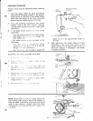
ADJUSTING UPPER
THRUST BEARING
NOTE: The
thrust
bearing
supports the
blade
from
the
rear and
will rotate when
the
blade
is
pushed
against it while
you
are cutting.
As
soon
as
you
stop cutting,
the
bearing should stop
rotating.
1.
To ad.iust, loosen
the
upper screw
on the
side
of
the upper blade
guide
assembly and
slide
the
bearing
forward
until
it is
approximately
1132" trom
the
back
of the
blade.
Tighten
screw.
Rotate upper wheel slightly clockwise
to
check clearance.
Readiust if
necessarv.
I
I
I
I
ST
NG
v
lo
L:
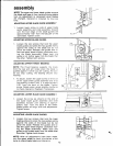
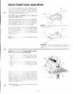
ADJUSTING
LOWER BLADE
GUIDE ASSEMBLY
1. Loosen
the
screw
(as
shown) on
the
side of
the
lower blade
guide
assembly and
slide
assembly
forward until bearing
is approxi'
mately
1132" trom
the
back of the
blade.
Blade
guides
will align with
this
adjustment.
Tighten
screw.
ADJUSTING LOWER
BLADE
GUIDES
1.
Loosen
the two screws
that
lock
the
lower
blade
guides
and
press
the
two
guides
evenly
against
the sides
of the
blade
but do not
pinch
the
blade. Release
the
guides
and ro-
tate the
upper wheel
slightly clockwise mov-
ing
the blade downward. Make
sure
one
guide
is not further away from
the
blade
than
the other.
Tighten
both screws.
NOTE: After
all
adjustments
have
been
made,
turn the
upper
wheel by
hand
(clockwise)
a few
turns to check
blade
travel and clearance.
12
(L