


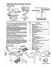
assembly
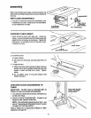
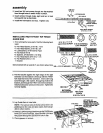
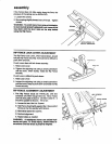
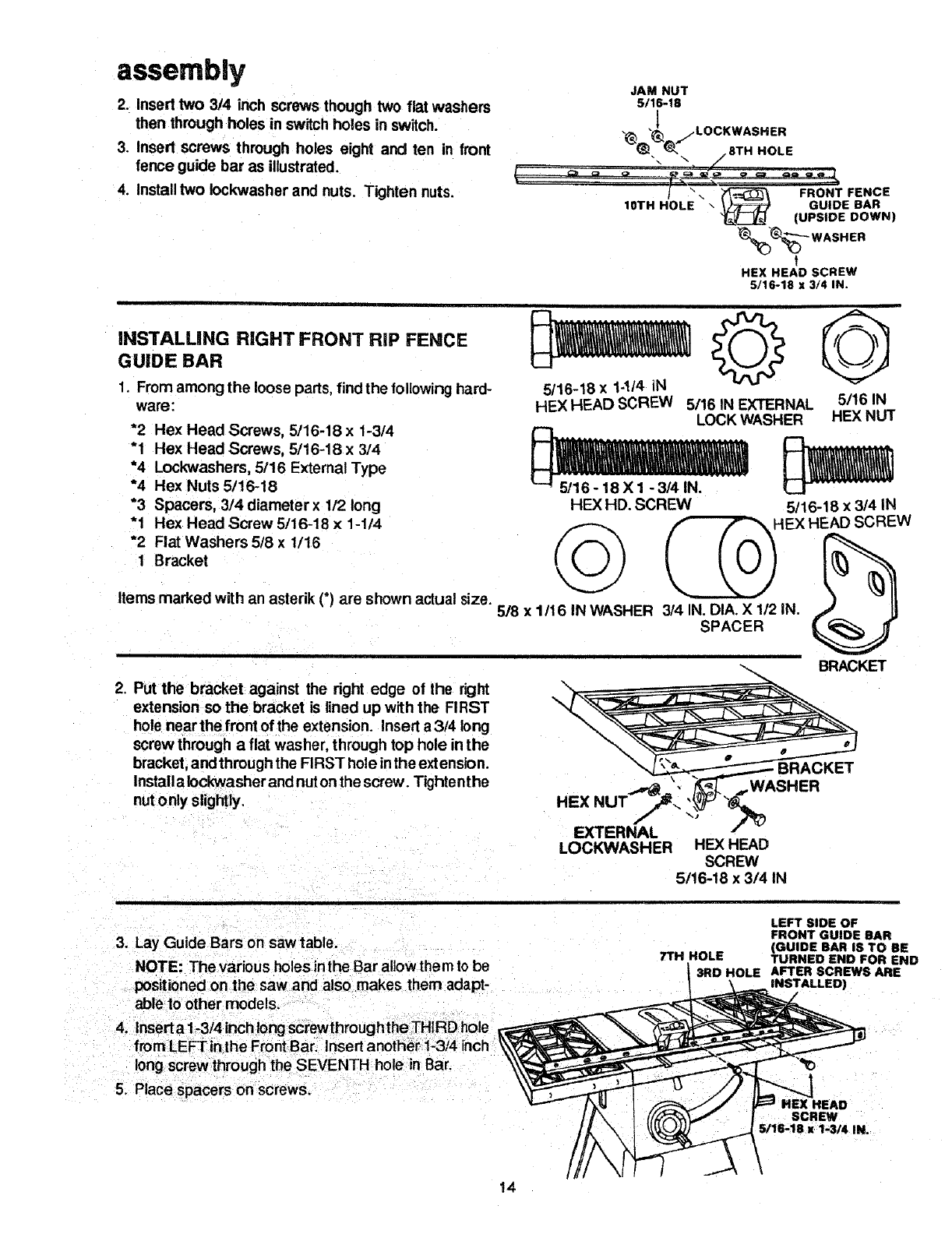
2. Insert two 3/4 inch screws though two flat washers
then through holes in switch holes in switch.
3. Insert screws through holes eight and ten in front
fence guide bar as illustrated.
4. Install two Iockwasher and nuts. Tighten nuts. J ".
IOTH HOLE
JAM NUT
5/16-18
LOCKWASHER
•.u,_.,,"_,.._ /8TH HOLE
FRONT FENCE
\ GUIDE BAR
(UPSIDE DOWN)
%%'--- WASHER
t
HEX HEAD SCREW
5/16-18 x 3/4 IN.
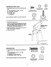
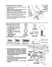
INSTALUNG RIGHT FRONT RiP FENCE
GUIDE BAR
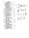
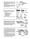
1. From among the loose parts, find the following hard-
ware;
5/16-18 x 1-!/4 iN
HEX HEAD SCREW 5/16 IN EXTERNAL
*2 Hex Head Screws, 5/16-18 x 1-3/4
"1 Hex Head Screws, 5/16-18 x 3/4
*4 Lockwashers, 5/16 External Type
*4 Hex Nuts 5/16-18
*3 Spacers, 3/4 diameter x 1/2 long
"1 Hex Head Screw 5/16-18 x 1-1/4
*2 Flat Washers 5/8 x 1/16
1 Bracket
Items marked with an asterik (*) are shown actual size.
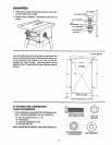
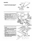
2. Put the bracket against the right edge of the right
extension so the bracket is lined up with the FIRST
hole near the front of the extension. Insert a 3/4 long
screw through a flat washer, through top hole in the
bracket, and through the FIRST hole in the extension.
Install a Iockwasher and nut on the screw. Tighten the
nutonly slightly.
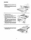
5/16 IN
LOCK WASHER HEX NUT
HEX HD. SCREW 5/16-18 x 3/4 IN
5/8 X 1/16 IN WASHER 3/4 IN, DIA. X 1/2 IN. .,_/ II
SPACER
BRACKET
HEX NU
EXTERNAL
LOCKWASHER HEX HEAD
SCREW
5116-18 x 3/4 IN
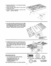
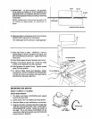
3. Lay Guide Bars on saw table.
NOTE: The various holes inthe Bar allow them to be
positioned on the saw and also makes them adapt-
able to other models.
4. Insert a 1-3t4 inch/ong screwthrough the THIRDhole
LEFT SIDE OF
FRONT GUIDE BAR
(GUIDE BAR I$ TO BE
TTH HOLE TURNED END FOR END
3RD HOLE AFTER SCREWS ARE
INSTALLED)
5. Place spacers on screws.
SCREW
S/16-18 x 1-3/4 IN.
\
14