


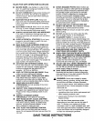
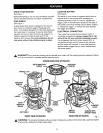
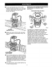
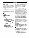
KNOWYOURROUTER
See Figure 1.
Before attempting to use any tool, familiarize yourself
with all operating features and safety requirements.
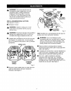
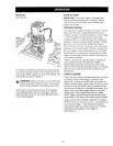
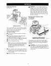
CHIP SHIELD
See Figure 1.
A clear plastic chip shield is installed on the front of
your router for protection against flying dust and
chips. The shield is designed to fit the front opening of
the router base. If necessary to remove chip shield,
squeeze the tabs on each end and pull outward. To
replace, squeeze the tabs at each end, fit into
opening, then release. For your protection, do not
use router without chip shield properly in place.
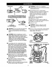
LOCK-ON BUTTON
See Figure 1.
The switch of your router is equipped with a lock-on
feature which is convenient when operating for
extended periods of time. To lock on, depress the
trigger, push in the lock button located on the side of
the handle, then while holding the lock button pushed
in, release the trigger. To release the lock, depress
the trigger and release.
ELECTRICAL CONNECTION
Your router has a precision built electric motor. It
should be connected to a power supply that is 120
volts, 60 Hz, AC only (normal household current).
Do not operate this tool on direct current (DC). A
substantial voltage drop will cause a loss of power
and the motor will overheat. If your router does not
operate when plugged into an outlet, double-check
the power supply.
,_ WARNING.'_'If parts are missing, do not operate router until the missing parts are replaced. Failure
any your
to do so could result in possible serious personal injury
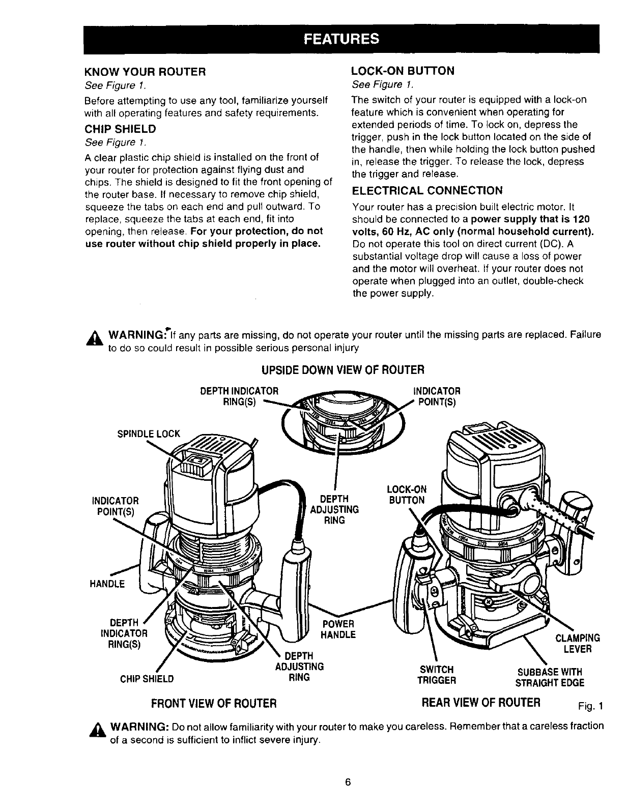
UPSIDE DOWN VIEW OF ROUTER
DEPTHINDICATOR INDICATOR
RING(S)
SPINDLELOCK
INDICATOR DEPTH BUTTON
\
HANDLE
DEPTH POWER
INDICATOR HANDLE CLAMPING
RING(S) LEVER
DEPTH
ADJUSTING SWITCH SUBBASEWITH
CHIPSHIELD RING TRIGGER STRAIGHTEDGE
FRONT VIEW OF ROUTER
REAR VIEW OF ROUTER
Fig. 1
_L, WARNING: Do not allow familiarity with your router to make you careless. Remember that a careless fraction
of a second is sufficient to inflict severe injury.
6