


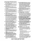
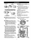
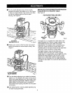
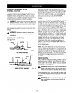
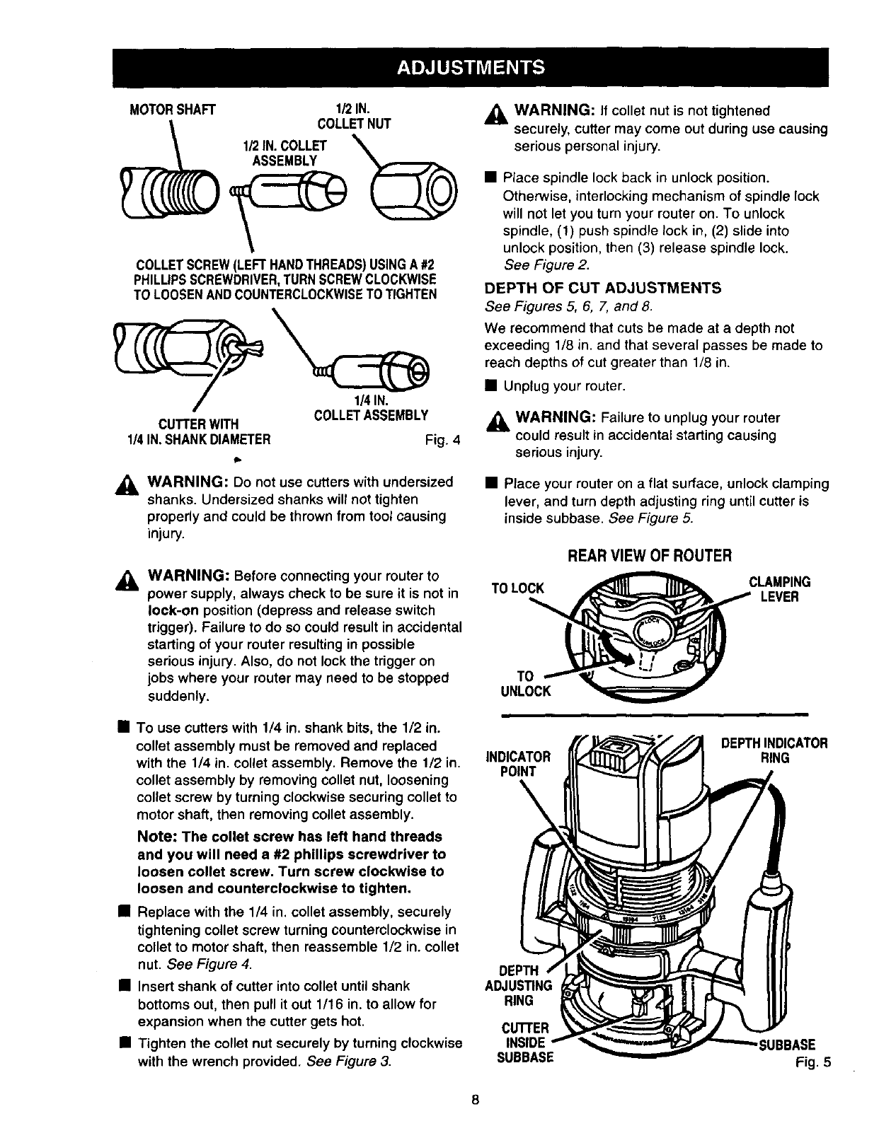
MOTORSHAFT 1/2IN.
COLLETSCREW(LEFTHANDTHREADS)USINGA#2
PHILLIPSSCREWDRIVER,TURNSCREWCLOCKWISE
TOLOOSENANDCOUNTERCLOCKWISETO TIGHTEN
COLLETASSEMBLY
CUTTERWITH
1/4IN.SHANKDIAMETER Fig. 4
_1= WARNING: Do not use cutters with undersized
shanks. Undersized shanks will not tighten
properly and could be thrown from tool causing
injury.
_, WARNING: Before connecting your router to
power supply, always check to be sure it is not in
lock-on position (depress and release switch
trigger). Failure to do so could result in accidental
starting of your muter resulting in possible
serious injury. Also, do not lock the trigger on
jobs where your router may need to be stopped
suddenly.
,_ WARNING: If collet nut is not tightened
securely, cutter may come out during use causing
serious personal injury.
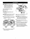
• Place spindle lock back in unlock position.
Otherwise, interlocking mechanism of spindle lock
will not let you turn your router on. To unlock
spindle, (!) push spindle lock in, (2) slide into
unlock position, then (3) release spindle lock.
See Figure 2.
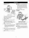
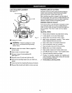
DEPTH OF CUT ADJUSTMENTS
See Figures 5, 6, 7, and 8.
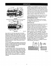
We recommend that cuts be made at a depth not
exceeding 1/8 in. and that several passes be made to
reach depths of cut greater than 1/8 in.
• Unplug your router.
_, WARNING: Failure to unplug your router
could result in accidental starting causing
serious injury.
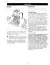
• Place your router on a flat surface, unlock clamping
lever, and turn depth adjusting ring until cutter is
inside subbase. See Figure 5.
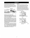
REAR VIEW OF ROUTER
TOLOCK CLAMPING
LEVER
TO
UNLOCK
• To use cutters with 1/4 in. shank bits, the 1/2 in.
collet assembly must be removed and replaced
with the 1/4 in. collet assembly. Remove the 1/2 in. INDICATOR
POINT
collet assembly by removing toilet nut, loosening
collet screw by turning clockwise securing collet to
motor shaft, then removing collet assembly.
Note: The collet screw has left hand threads
and you will need a #2 phillips screwdriver to
loosen collet screw. Turn screw clockwise to
loosen and counterclockwise to tighten.
• Replace with the 1/4 in, collet assembly, securely
tightening collet screw turning counterclockwise in
collet to motor shaft, then reassemble 1/2 in. collet
nut. See Figure 4. DEPTH
• Insert shank of cutter into collet until shank ADJUSTING
bottoms out, then pull itout 1/16 in. to allow for RING
expansion when the cutter gets hot. CUTTER
• Tighten the collet nut securely by turning clockwise INSIDE
with the wrench provided. See Figure 3. SUBBASE
DEPTHINDICATOR
RING
SUBBASE
Fig. 5
8