


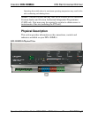
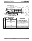
Crestron DIN-1DIMU4 DIN Rail Universal Dimmer
Connectors, Controls & Indicators (Continued)
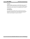
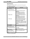
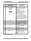
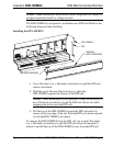
# CONNECTORS
1
,
CONTROLS & INDICATORS
DESCRIPTION
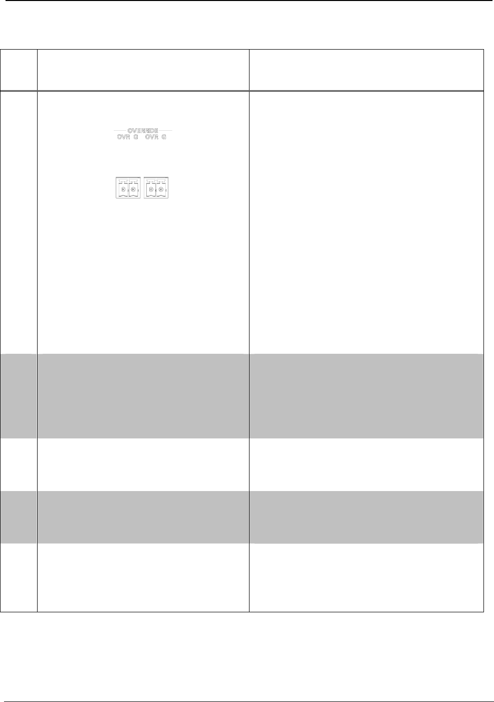
3 OVERRIDE
with LEDs and BUTTON
(2) 2-pin 3.5 mm detachable
terminal blocks, paralleled;
Maximum wire size: 1.5 mm
2
(16 AWG)
Sensing input for external
low-voltage contact closure;
Activates Override mode when a
closure is present;
Minimum closure rating:
10 mA (per module) at 24 Volts
(1) Red LED and (1) miniature
pushbutton for enabling Override
mode and saving override presets.
For more information, refer to
“
Operation” which starts on page
24.
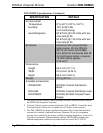
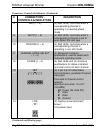
4 PWR (1) Green LED, solid on indicates
AC line power is connected to
either LIVE terminal, blinking
indicates power from Cresnet but
no AC power
5 NET (1) Yellow LED, indicates
communication with the control
processor
6 RESET (1) Recessed miniature
pushbutton, resets internal
processor
7 FWD (1 – 4) (4) Red LEDs, illuminate when a
corresponding channel is
operating in a forward phase
mode
(Continued on following page)
Operations & Installation Guide – DOC. 6668A DIN Rail Universal Dimmer: DIN-1DIMU4 • 9