


DIN Rail Universal Dimmer Crestron DIN-1DIMU4
Connectors, Controls & Indicators (Continued)
# CONNECTORS
1
,
CONTROLS & INDICATORS
DESCRIPTION
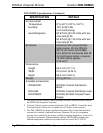
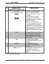
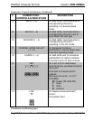
8 REV (1 – 4) (4) Red LEDs, illuminate when a
corresponding channel is
operating in a reverse phase
mode
9 AUTO (1 – 4) (4) Red LEDs, illuminate when a
corresponding channel is set to
auto-detect the load type
10 NON-DIM (1 – 4) (4) Red LEDs, illuminate when a
corresponding channel is
operating in non-dim mode
11 CHANNEL MODE SELECT
(1 – 4)
(4) Recessed miniature
pushbuttons, used to select each
channel’s operating mode
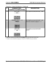
12 LOADS (1 – 4) (4) Red LEDs and (4) miniature
pushbuttons for status indication
and local control of each channel
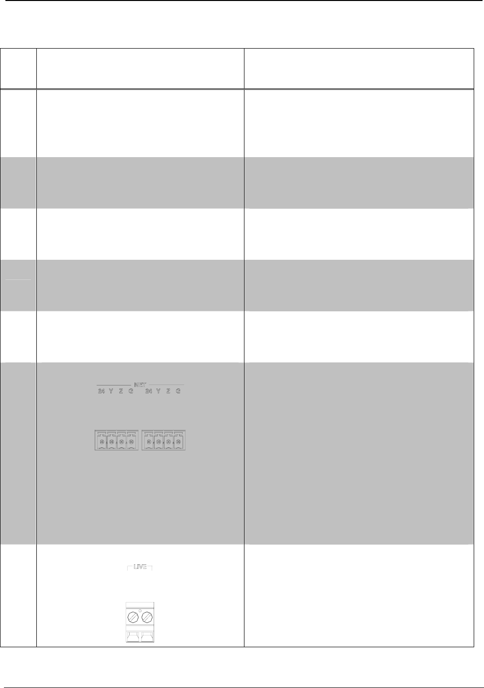
13 NET
(2) 4-pin 3.5 mm detachable
terminal blocks, paralleled Cresnet
slave port
Connects to Cresnet control
network.
Maximum wire size: 1.5 mm
2
(16 AWG)
24: Power (24 Volts DC)
Y: Data
Z: Data
G: Ground
14 LIVE
(2) Captive screw terminals
2
,
brown;
Line power input
(Continued on following page)
10 • DIN Rail Universal Dimmer: DIN-1DIMU4 Operations & Installation Guide – DOC. 6668A