


Crestron GLS-LCL
CLOSED-LOOP PHOTOCELL LIGHT SENSOR
Operations & Installation Guide
FCC Compliance Statement:
Further Inquiries
If you cannot locate specific information or have questions after reviewing this guide, please take
advantage of Crestron's award winning customer service team by calling Crestron at
1-888-CRESTRON [1-888-273-7876].
You can also log onto the online help section of the Crestron website (www.crestron.com/onlinehelp) to
ask questions about Crestron products. First-time users will need to establish a user account to fully
benefit from all available features.
Future Updates
As Crestron improves functions, adds new features and extends the capabilities of the GLS-LCL units,
additional information may be made available as manual updates. These updates are solely electronic
and serve as intermediary supplements prior to the release of a complete technical documentation
revision.
Check the Crestron website periodically for manual update availability and its relevance. Updates are
identified as an “Addendum” in the Download column.
This device complies with part 15 and part 18 of the FCC rules. Operation is subject to the following
two conditions: (1) This device must not cause harmful interference, and (2) This device must accept
any interference received, including interference that may cause undesired operation.
The GLS-LCL Closed-Loop Photocell responds to ambient light
levels within an occupied space and provides an analog voltage
proportionate to the ambient light level.
The ambient light measured is the light from any light source in the
visible spectrum. The photocell does not distinguish between natural
sunlight and artificial light. It contains a sensor which is color and
spatially corrected to provide a true representation of changes in
lighting levels that the human eye perceives.
The sensor measures the ambient light that actually falls upon it
within a 60º cone extending downward from the sensor (refer to
“Field of View” illustration on the second page). This is the light that
gets reflected to the ceiling from the walls, floor and furniture.
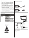
GLS-LCL Specifications
NOTE: Care must be taken when choosing the mounting location.
It is recommended that the sensor be mounted directly above the
work space, such as a desk, conference table or computer terminal.
Mounting location is important because the ambient light level will
be different at different points in the
room, depending on the location
of the windows, lighting fixtures, wall colors, etc. The ambient light at
the doorway can be much less than that at the windows, corners of
the room, or especially on the ceiling. Therefore, it is important to
measure the ambient light level over the workplace.
DESCRIPTION
• To be installed and/or used in accordance with appropriate electrical codes and
regulations.
• If you are unsure about any part of these instructions, consult a qualified electrician.
WARNINGS, CAUTIONS & NOTES
When wiring the Cresnet
®
network, consider the following:
• Use Crestron Certified Wire.
• Use Crestron power supplies for Crestron equipment.
• Provide sufficient power to the system.
NETWORK WIRING
CAUTION: Insufficient power can lead to unpredictable results or damage to the
equipment. Please use the Crestron Power Calculator to help calculate how much power
is needed for the system. (www.crestron.com/calculators).
WARNING: To avoid fire, shock, or death; turn off power at circuit breaker or fuse and
test that power is off before wiring!
NOTES: Observe the following points regarding sensor installation.
PREPARING AND CONNECTING WIRES
Strip the ends of the wires approximately 1/2”. Use care to avoid nicking the conductors.
Twist together the ends of the wires that share a connection and tin the twisted
connection. Apply solder only to the ends of the twisted wires. Avoid tinning too far up
the wires or the end becomes brittle.
INSTALLATION
The GLS-LCL can either be fastened onto the ceiling surface, flush
mounted into the ceiling, or installed in a 4 inch (10.2 cm) round or
octagonal outlet box, depending on ceiling material and local codes.
1. To fasten the photocell to the ceiling surface, attach the outer
shell provided to the ceiling at the desired location using two
#4 screws and appropriate anchor hardware, where neces-
sary. For concealed wiring, access to the space above the
ceiling is required, as well as a hole in the ceiling above the
photocell to connect the wires from the optional GLS-SIM or
other Crestron interface device.
Make all connections as described in Steps 3 through 8.
Carefully feed the wires into the hole and press the Photocell
body into the outer shell until the rim is flush with the shell.
NOTE: If wiring is to be run exposed along the ceiling, carefully
trim the plastic from the indentation in the side of the outer shell
and lay the photocell wires through it before tightening the shell
onto the ceiling.
2. To flush mount into the ceiling (only allows concealed wiring,
the outer shell is
not used), cut a 2 inch (5.1 cm) diameter
hole through the ceiling. Make all connections as described in
Steps 3 through 8. Carefully feed the wires back through the
hole and press the GLS-LCL into the hole until the rim is flush
with the ceiling.
Crestron Electronics, Inc. Operations & Installation Guide-DOC. 6773A
15 Volvo Drive Rockleigh, NJ 07647 (2023020)
Tel: 888.CRESTRON 12.08
Fax: 201.767.7576 Specifications subject to
www.crestron.com change without notice.
SPECIFICATION
DETAILS
Power Consumption
1W (42mA @ 24VDC)
Field of View Coverage 60° Cone
Output 0 - 10VDC (0 - 70 footcandles)
Recommended Mounting Location Directly above work space
MOUNTING