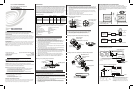
Crestron Electronics, Inc. Operations & Installation Guide-DOC. 6769A
15 Volvo Drive Rockleigh, NJ 07647 (2023016)
Tel: 888.CRESTRON 12.08
Fax: 201.767.7576 Specifications subject to
www.crestron.com change without notice.
FCC Compliance Statement:
This device complies with part 15 and part 18 of the FCC rules. Operation is subject to the following
two conditions: (1) This device must not cause harmful interference, and (2) This device must accept
any interference received, including interference that may cause undesired operation.
Further Inquiries
If you cannot locate specific information or have questions after reviewing this guide, please take
advantage of Crestron's award winning customer service team by calling Crestron at 1-888-CRESTRON
[1-888-273-7876].
You can also log onto the online help section of the Crestron website (www.crestron.com/onlinehelp) to
ask questions about Crestron products. First-time users will need to establish a user account to fully
benefit from all available features.
Future Updates
As Crestron improves functions, adds new features and extends the capabilities of the GLS-ODT-C units,
additional information may be made available as manual updates. These updates are solely electronic
and serve as intermediary supplements prior to the release of a complete technical documentation
revision.
Check the Crestron website periodically for manual update availability and its relevance. Updates are
identified as an “Addendum” in the Download column.
INSTALLATION INSTRUCTIONS
These instructions include three typical installation options (A, B, and C). Choose one that
best suits your needs. Other methods may be possible but they are not described here.
Parts Supplied
Sensor (1) Threaded Rod (1) and Hex nut (1)
#8-32 x 1/2” screw (2) Half Mask (1)
#8-32 x 1-1/2” screw (2) 360º Perforated Mask (1)
#8x32 Washer and Nut (2) Plastic Washer (1)
Tools/Equipment Required (not supplied)
Phillips Screwdriver Electrical Tape
Pliers Pencil
Diagonal Cutters
Model/Feature Basics
The Occupancy Sensor is a low-voltage infrared and ultrasonic sensor that works with the
GLS-SIM (or other compatible interface) to automatically control lighting. The exact behavior
of the sensor can be configured via software, but the sensor is typically used to turn lights on
when a room or area is occupied, and to shut them off when the room or area is vacated.
The sensor continually analyzes and adjusts to changing conditions. The sensor uses the
latest microprocessor-based technology which permits it to continually adjust and optimize its
performance. The combination of ultrasonic (doppler shift) motion detection, which gives
maximum sensitivity, and infrared motion detection, which gives higher false triggering
immunity, yields a sensor with excellent performance.
DESCRIPTION
• To be installed and/or used in accordance with appropriate electrical codes and regulations.
• If you are unsure about any part of these instructions, consult a qualified electrician.
• Sensors must be mounted on a vibration free surface.
• All sensors must be mounted at least 6 feet away from air vents.
• Do not mount sensors closer than 10 feet from each other.
• Do not touch the inner surface of the lens. Clean outer surface with a damp cloth only.
WARNINGS, CAUTIONS & NOTES
When wiring the Cresnet
®
network, consider the following:
• Use Crestron Certified Wire.
• Use Crestron power supplies for Crestron equipment.
• Provide sufficient power to the system.
NETWORK WIRING
CAUTION: Insufficient power can lead to unpredictable results or damage to the
equipment. Please use the Crestron Power Calculator to help calculate how much power
is needed for the system. (www.crestron.com/calculators).
WARNING: To avoid fire, shock, or death; turn off power at circuit breaker or fuse and
test that power is off before wiring!
NOTES: Observe the following points regarding sensor installation.
PREPARING AND CONNECTING WIRES
Strip the ends of the wires approximately 1/2”. Use care to avoid nicking the conductors. Twist together
the ends of the wires that share a connection and tin the twisted connection. Apply solder only to the
ends of the twisted wires. Avoid tinning too far up the wires or the end becomes brittle.
Crestron GLS-ODT-C-500/1000/2000
DUAL-TECHNOLOGY CEILING MOUNTED
OCCUPANCY SENSOR
Operations & Installation Guide
Coverage
500 sq. ft
1000 sq. ft.
2000 sq. ft.
Suggested
Mounting Location
Mount in corner/
over doorway
Mount in center
of room/area
Mount in center
of room/area
Model No.
GLS-ODT-C-500
Description
1-Way Dual-Technology
2-Way Dual-Technology
2-Way Dual-Technology
Operating
Frequency
40KHz
40KHz
32KHz
Current
Consumption
30mA
40mA
32mA
GLS-ODT-C-1000
GLS-ODT-C-2000
24 1 2 G
optional
Sensor
#2
()
Red
Black
Black
Red Red
*
Blue
*
Sensor
#1
Black
Red
Blue*
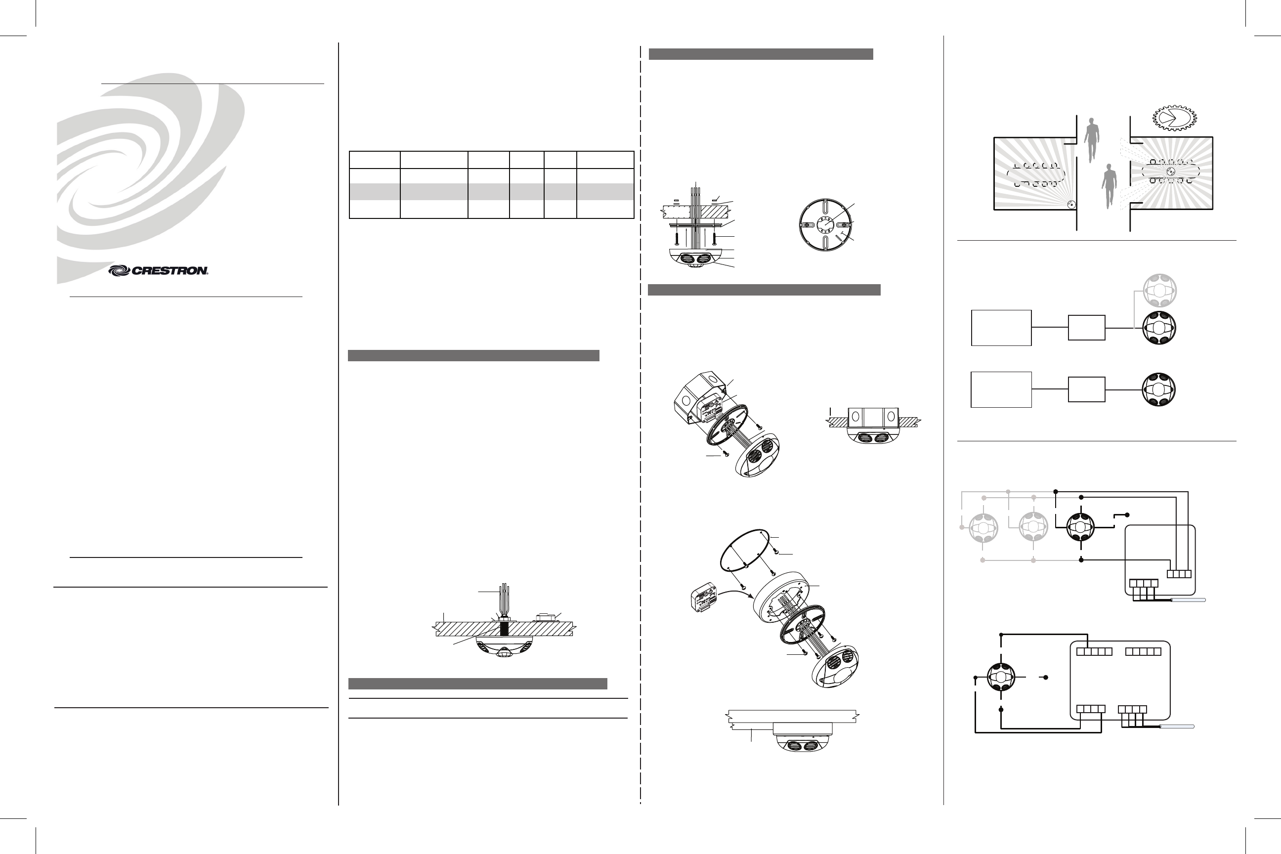
Connecting Sensors to the GLS-SIM
Connecting Sensors to the DIN-IO8 or Equivalent**
All wires from sensor to GLS-SIM
must be 24 AWG, minimum.
* To incorporate the internal photocell, connect
gray wire to GLS -SIM and cap off blue wire
from sensor.
Gray* (cap off)
Gray*
(cap off)
–SENSOR–
––– NET–––
24 Y Z G
Use CRESNET
-
P or
CRESNET
-
NP wire only
GLS-SIM
Sensor
#1
optional
Sensor
#3
()
To Control
System
G 1 2 3 4
–––
NET
G 1 2 3 4
24 Y Z G
24 Y Z G
–––
To Control
System
–––
–––
I/O
DIN-IO8
NOTE: The same Crestron power supply MUST be used to
power both the sensors and the interface device (e.g., DIN-IO8).
Otherwise, there is a risk of damage to the interface device.
*To incorporate the internal photocell, connect the gray wire to
the DIN-IO8 (or other interface device) and cap off the blue wire
from the sensor.
WIRING DIAGRAMS
Black
Blue
Blue*
**The following Crestron devices may be used to
integrate the sensors into a Cresnet system by
following the schematic shown here:
DIN-IO8 DIN-AP2 PAC2 PRO2
AV2 CP2E MP2E CNXIO16
Any Crestron product with Versiports
Use CRESNET
-
P or
CRESNET
-
NP wire only
By masking two sections,
you can block hallway traffic
Masking is not required in a corner
mounting application. The sensor
can not see hallway traffic.
Mask
MOUNTING/MASKING LOCATION DIAGRAM
Option A. Drop Ceiling Installation Using Supplied Threaded Rod
1. Select the location for mounting the sensor and proper masking for your
application. (Refer to Mounting/Masking Location Diagram).
2. Use the supplied threaded rod or other means to make a hole (1/2" to 1") in the
ceiling tile just large enough to pass the shaft of the threaded rod through.
3. Insert the sensor wires through the flared end of the threaded rod. Position the
threaded rod to the base of the sensor.
4. Insert the flared end of the threaded rod into the opening in the bottom of the
sensor and twist to lock into place.
5. Push the wires into the hole in the ceiling tile and insert the threaded rod until the
sensor is flush with the tile.
6. Insert wires through the hole in the included washer, then place the washer over
the rod and secure in position using the included hex nut.
7. Connect low voltage wires from the GLS-SIM or other Crestron
®
device as shown in
the wiring diagram. Twist strands of each lead tightly and, with circuit conductors,
push firmly into appropriate wire connector. Screw connectors on clockwise making
sure that no bare conductor shows below the wire connectors. Secure each
connector with electrical tape.
8. Rotate the sensor to the desired orientation. Note that the sensor base and
backcover are keyed. To lock the device in place, ensure that the arrows are not
aligned.
9. Restore power at circuit breaker or fuse. INSTALLATION IS COMPLETE.
Mounting to Drop Ceiling Using Threaded Rod
Low-Voltage Wires
NOTE: Wires routed through
the Threaded Rod
Drop Ceiling
1" thick maximum
Nut
Washer
Threaded Rod
5. Connect low voltage wires from the GLS-SIM or other Crestron device as shown in the
wiring diagram. Twist strands of each lead tightly and, with circuit conductors, push
firmly into appropriate wire connector. Screw connectors on clockwise making sure
that no bare conductor shows below the wire connectors. Secure each connector with
electrical tape.
6. Push wire connections through the center hole of the back cover and into the ceiling.
7. Secure the sensor body to the back cover by aligning the arrows. Lock it by turning
the sensor such that the arrows do not line up.
8. Rotate the sensor to the desired orientation.
9. Restore power at the circuit breaker or fuse. INSTALLATION IS COMPLETE.
Low-Voltage Wires
Wallboard
Ceiling
Sensor
Back Cover
Sensor Base
Keylock Arrow
Mounting Screws
(2 places)
Sensor Front Cover
Back Cover open center to
route Low-Voltage Wires
Mounting Screw
Back Cover internal
surface shown
Back Cover shown mounted
on ceiling with screws
Nut (2 places)
Washer (2 places)
Mounting to Drop Ceiling Using Screws
OPTION B. Drop Ceiling Installation Using Screws
NOTE: You may use the mounting screws, nuts and washers included, or screws in
combination with commercially available wall anchors.
1. Select the location for mounting of the sensor and proper masking for your application
(Refer to Mounting/Masking Location Diagram).
2. Make a hole in the ceiling tile large enough to pass the wire connections and wire nuts
through (approximately 1" diameter).
3. Remove the back cover of the sensor. Hold the back cover and body of the sensor and
rotate until the two arrows line up, and pull them apart.
4. Install back cover of the ceiling sensor to the wallboard or drop ceiling using the
included screws, nuts and washers, or screws in combination with commercially
available wall anchors.
OPTION B. Drop Ceiling Installation Using Screws (Cont’d)
OPTION C. Back Box or Surface Mount Raceway Installation
#8-32 Screws
(2 places)
Octagon Back Box
4" x 1 1/2" deep
Low-Voltage
Wires
Drop Ceiling
Mounting to Octagon Back Box Installed Flush to Drop Ceiling
TYPICAL APPLICATION DIAGRAMS
GLS-SIM
Cresnet
®
GLS-ODT-C-500/1000/2000
Up to Three
in
Parallel
The supplied masks mount in the sensor front cover. The half mask is supplied
pre-mounted to demonstrate the mounting method. The perforated mask has twelve 30º
removable segments that allow you to mask particular areas to prevent undesireable
triggers from affecteng the sensor operation. The following illustrations provide typical
application examples.
1. Select the location for mounting of the sensor and proper masking for
your application (Refer to Mounting/Masking Location Diagram).
2. Refer to the suggested mounting option illustrations below.
Mounting to Round Fixture with Raceway for Wallboard Ceiling Installation
Wire Mold Back Cover
Back Cover Screws
(4 places)
Wire Mold Round Fixture
(for raceway mount)
Mounting Screws
(4 places)
Low-Voltage Wires
Wallboard Ceiling
Wire Mold Raceway
(use applicable fittings)
DIN-IO8
GLS-ODT-C-500/1000/2000
Cresnet
®
GLS-SIM (Optional)
GLS-SIM (Optional)
GLS-SIM
(Optional)
Crestron
2-Series Control
Processor or
CLS-C6
Crestron
2-Series Control
Processor