


12
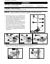
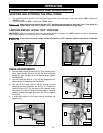
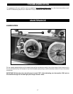
5. Thread the two speed-changing levers (W) Fig. 22 into the speed changing hub.
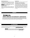
6. Thread the speed range-changing lever (X) Fig. 23 into the hub.
Fig. 22
Fig. 23
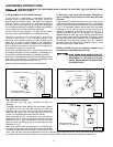
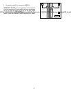
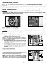
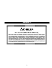
MOUNTING DRILL PRESS ON A SUPPORTING SURFACE
Fig. 24
A
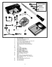
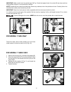
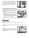
MOUNTING THE DRILL PRESS ON A PLYWOOD BASE
If you do not fasten your machine permanently, then you must fasten the drill press to a plywood mounting board to prevent
it from tipping over. Use a good grade of 3/4" or thicker plywood. DO NOT make the mounting board from particle board.
1. Start with a 21" x 28" or larger piece of plywood. Drill two 3/8" diameter holes (B) Fig. 25 that match the mounting holes
(A) Fig. 24 of the drill press base.
2.
Fasten the drill press base to the mounting board using the carriage bolts, flat washers, lockwashers, and hex nuts
(C) Fig. 25, furnished with your drill press. The holes for the carriage bolt heads and flat washers under the board
must be countersunk so that the bolt heads are flush or below the bottom surface of the board. Make sure to use
a flat washer, lock washer and hex nut above the drill press base.
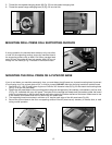
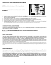
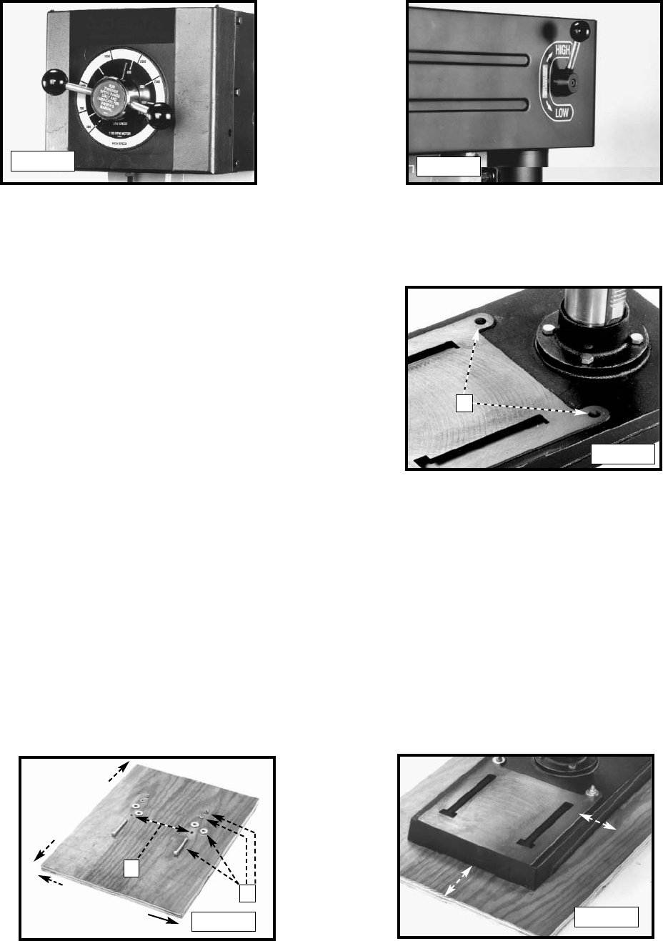
3. The supporting board must extend a minimum of 3" beyond each edge of the drill press base (Fig. 26).
4. Secure the plywood base to the floor or supporting surface if the drill press has any tendency to vibrate, slide, or walk
during normal operation.
Fig. 26
3" Min.
3" Min.
If, during operation, the machine has a tendency to tip over, slide,
or walk on the supporting surface, secure the machine base to
the supporting surface with an M8x1.25x125mm carriage head
screw, 8.5mm flat washer, 8.5mm lock washer, M8x1.25 hex nut
through the two holes (A) Fig. 24 located in the machine base.
28" MINIMUM
21" MINIMUM
C
Fig. 25
B