


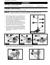
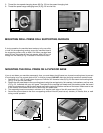
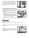
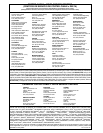
1. Insert the bit into the chuck.
2. Lower the chuck (C) Fig. 34, and the drill bit to your chosen
depth by rotating the pinion shaft handles (D). Lock the quill in
position by tightening the quill locking lever (E).
NOTE: The quill locking lever (E) is spring-loaded. Change it by
pulling out on the handle and repositioning the hub of the handle on
the nut located underneath the hub.
3. Depress the spring-loaded button (F) Fig. 34 and move the stop
nut (A) until the bottom of the nut (A) contacts the stop (G).
Loosen the quill locking-lever (E) to allow the chuck and drill bit
to return to the up position.
4. Connect the machine to the power source and drill a test hole to
check the adjustment. Readjust, if necessary, by rotating the
stop nut (A) Fig. 34 for fine adjustment. You will not have to
depress the button (F) while rotating the stop nut (A) for fine
adjustment.
14
When you want to drill a number of holes to the same depth, use the stop nut (A) Fig. 34 on the threaded stop rod (B).
DRILLING HOLES TO DEPTH
DISCONNECT MACHINE FROM POWER SOURCE.
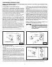
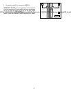
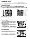
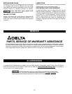
VARIABLE SPEED CONTROL
Turn variable speed pilot-wheel handles (A) Fig. 32 ONLY WHEN THE MOTOR IS RUNNING.
Turn the pilot-wheel handles (A) clockwise to increase speed and counter-clockwise to decrease speed. The pointer
(B) indicates the speed of the drill press.
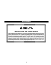
SPEED RANGE CONTROL
Turn the speed-range control lever (A) Fig. 33 ONLY WHEN THE MOTOR IS RUNNING.
The handle (A) in the “HIGH” position produces a speed range of 500 to 3200 RPM. The handle (A) in the “LOW”
position produces a speed range of 150 and 1100 RPM.
Fig. 32 Fig. 33
B
A
A
A
Fig. 34
A
B
C
D
E
F
G
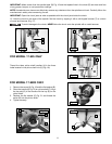
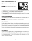
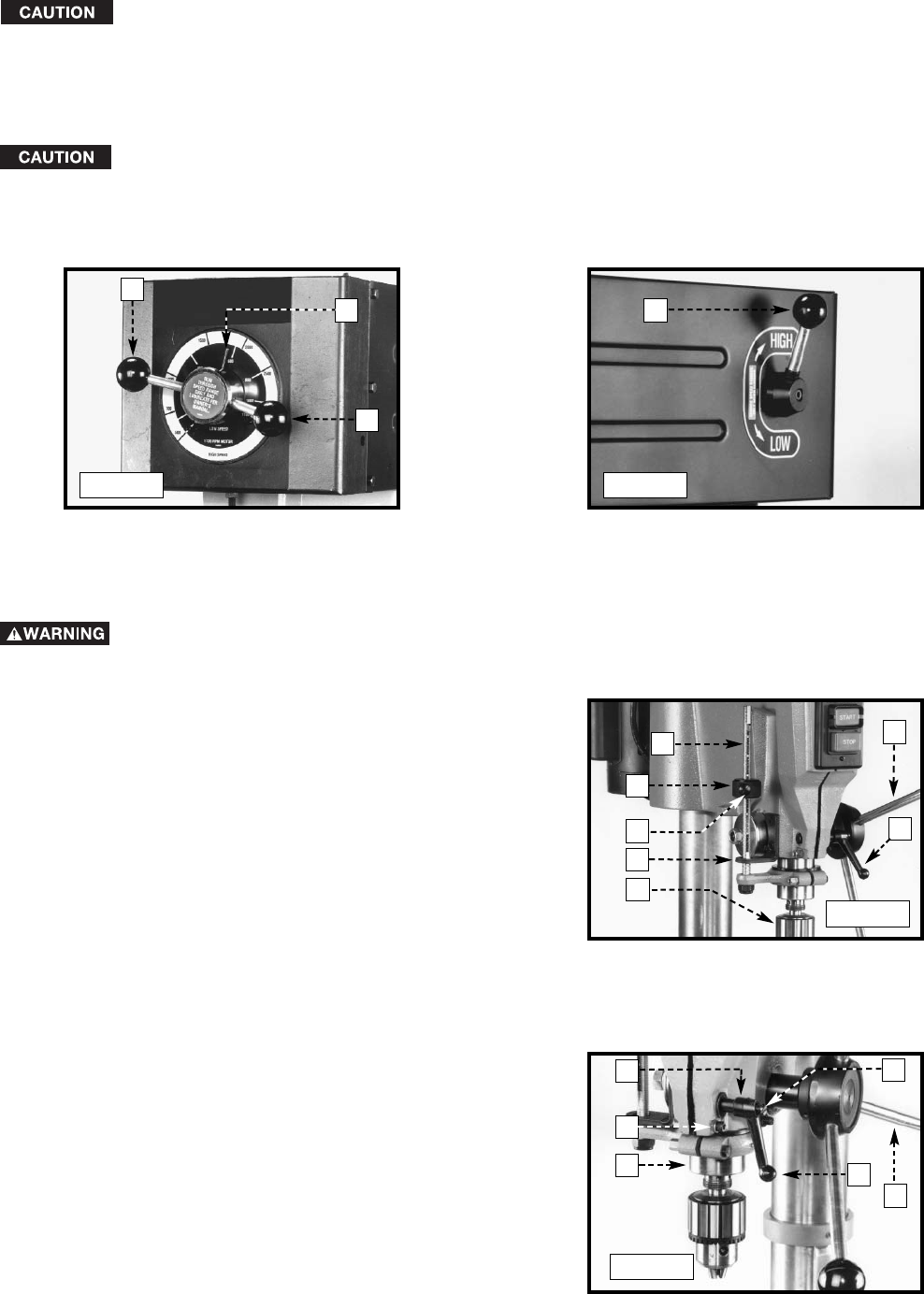
QUILL ADJUSTMENTS
To raise and lower the spindle, turn the pilot wheel (A) Fig. 35. To
lock the quill (B), tighten the quill locking lever (C).
NOTE: The quill-locking lever (C) is spring-loaded. To change
the position of the handle, pull out on the handle (C), and
reposition the hub (F) on the nut (D) located underneath the hub
Fig. 35
A
C
B
D
E
F