


10
Fig. 12
Y
X
Fig. 13
Z
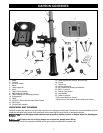
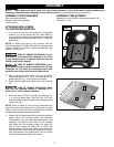
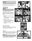
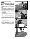
ASSEMBLING HEADSTOCK
TO COLUMN AND BASE
To assemble the headstock to the column:
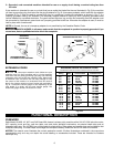
1. Place the drill press head (P) Fig. 9 on the column as far
as it will go.
NOTE: Be sure the head-locking screws (R) are do not
block the drill press head from fully seating on the column.
To reduce the risk of injury, always use at
least two people when lifting.
2. Align the head (P) Fig. 10 with the table (Q) and the
base (B).
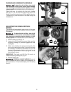
3. Tighten the two head-locking screws (R) Fig. 9 with the
5 mm hex wrench supplied.
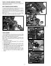
INSTALLING THE CHUCK
To reduce the risk of injury, turn unit off
and disconnect it from power source before installing
and removing accessories, before adjusting or when
making repairs. An accidental start-up can cause injury.
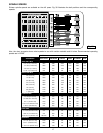
IMPORTANT: Make certain that the tapered hole in the
bottom of spindle (U) Fig. 11, and the taper on the spindle
adapter (V) are clean and free of grease, lacquer or rust-
preventive coatings.
NOTE: Remove the rust-preventative oil from the chuck
using a soft cloth moistened with mineral spirits, paint
thinner or denatured alcohol.
Push the spindle adapter (V) Fig. 11 into the spindle (U).
making certain that the tang (W) engages the mating slot
inside the spindle (U).
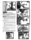
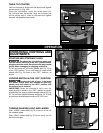
NOTICE
RISK OF PROPERTY DAMAGE. To avoid
damage to the laser, prevent the cleaning solution from
coming in contact with the laser pod. You can clean the
laser pod with a dry cotton cloth.
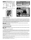
IMPORTANT: Make certain the spindle taper (X) Fig. 12, and
tapered hole in chuck (Y) are clean and free of any grease,
lacquer or rust preventive coatings.
NOTE: Remove the rust-preventative oil from the chuck
using a soft cloth moistened with mineral spirits, paint
thinner or denatured alcohol.
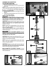
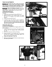
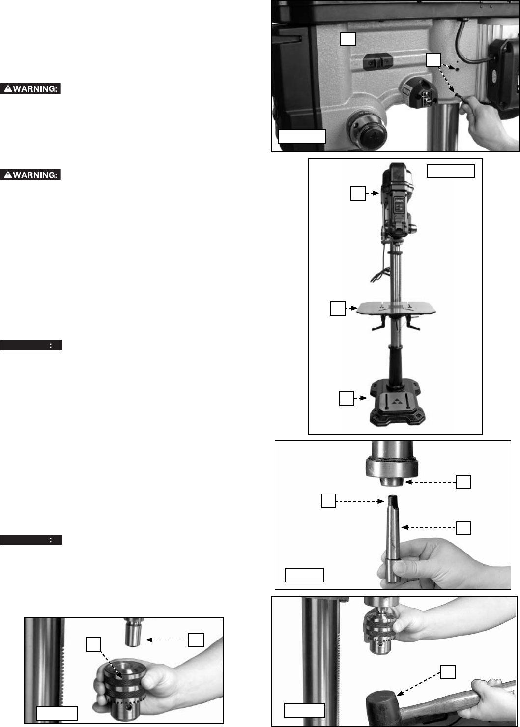
IMPORTANT: Rotate the chuck until the chuck jaws are
fully retracted inside the chuck. Hold the chuck on the taper
of the spindle. Tap it with a soft-tip hammer (Z) Fig. 13 or a
block of wood and hammer to set the chuck.
NOTICE
RISK OF PROPERTY DAMAGE. To avoid
damage to the chuck, NEVER drive the chuck on the spindle
with a metal hammer.
Fig. 11
U
V
W
P
Fig. 9
R
P
Fig. 10
Q
B