


5
HAZARDOUS RADIATION. Use or modi-
fication of the tool for anything other than its designed
purpose may result in hazardous radiation exposure.
• The label on your tool may include the following symbols.
V ................volts mW ....... milliwatts
.....Laser warning nm ........ wavelength in
.....symbol .............nanometers
II .................Class II Laser IIIa ........Class IIIa Laser
.............. alternating current ......direct current
W ............... watts Hz ......... hertz
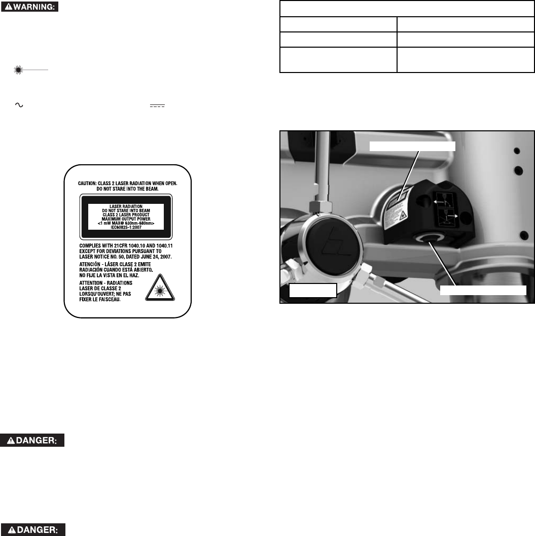
WARNING LABELS
For your convenience and safety, the following label is on your
laser:
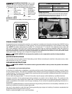
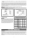
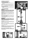
LASER APERTURES
The laser aperture on each laser pod (on both sides of the drill press
head) is located on each pod as shown in Figure A. Also, the warn-
ing label is located on the drill press as shown:
Laser Apertures
Laser Warning Label
Fig. A
LASER SPECIFICATIONS
LIGHT SOURCE
Dual semiconductor laser diode
LASER WAVELENGTH
630nm – 680nm Visible
LASER POWER
<1mw (each beam) CLASS II
LASER PRODUCT
POWER CONNECTIONS
A separate electrical circuit should be used for your machines. A suitable circuit should not be less than AWG12/3 wiring
where the ground wire is attached to an earth ground. The circuit should be protected by a circuit breaker or time delay
fuse. NOTE: Time delay fuses should be marked “D” in Canada and “T” in the US. If an extension cord is used, use
only 3-wire extension cords which have 3-prong grounding type plugs and matching receptacle which will accept the
machine’s plug. Before connecting the machine to the power line, make sure the switch (s) is in the “OFF” position and
be sure that the electric current is of the same characteristics as indicated on the machine. All line connections should
make good contact. Running on low voltage will damage the machine.
SHOCK HAZARD. Do not expose the machine to rain or operate the machine in damp locations.
MOTOR SPECIFICATIONS
Your machine is wired for 120 volt, 60 HZ alternating current. Before connecting the machine to the power source, make
sure the switch is in the “OFF” position.
GROUNDING INSTRUCTIONS
SHOCK HAZARD. This machine must be grounded while in use to protect the operator from electric
shock.
1. All grounded, cord-connected machines:
In the event of a malfunction or breakdown, grounding provides a path of least resistance for electric current to reduce
the risk of electric shock. This machine is equipped with an electric cord having an equipment-grounding conductor and
a grounding plug. The plug must be plugged into a matching outlet that is properly installed and grounded in accordance
with all local codes and ordinances.
Do not modify the plug provided - if it will not fit the outlet, have the proper outlet installed by a qualified electrician.
Improper connection of the equipment-grounding conductor can result in risk of electric shock. The conductor with
insulation having an outer surface that is green with or without yellow stripes is the equipment-grounding conductor. If
repair or replacement of the electric cord or plug is necessary, do not connect the equipment-grounding conductor to a
live terminal.
Check with a qualified electrician or service personnel if the grounding instruction are not completely understood, or if in
doubt as to whether the machine is properly grounded.
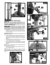
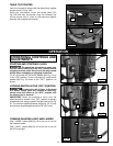
Use only 3-wire extension cords that have 3-prong grounding type plugs and matching 3-conductor receptacles that
accept the machine’s plug, as shown in Fig. B.
Repair or replace damaged or worn cord immediately.