


6
DESCRIPTION OF OPERATION
Air Compressor Pump: To compress air, the piston
moves up and down in the cylinder. On the downstroke,
air is drawn in through the air intake muffler (valves). The
exhaust valve remains closed. On the upstroke of the
piston, air is compressed. The intake valves close and
compressed air is forced out through the exhaust valve
and then through the air hose.
Adjustable Pressure Valve: The pressure valve controls
the amount of pressure going from the air compressor to
the accessory. The pressure adjusting valve can be used
to set approximate pressure between 10 and 125 P.S.I.
(125 P.S.I. is the highest pressure this compressor will
deliver). It is normal for the adjustable pressure valve to
release air during operation.
Accumulator Tank: Your accumulator tank is equipped
with a relief (pop-off) valve to prevent an over pressure
condition in the tank. This 2 gallon tank is not designed to
store air, but rather to provide the additional volume of
compressed air necessary to operate a wide variety of air
tools. When starting your compressor, attach the tool to
the hose, set the pressure adjusting valve at the required
pressure, wait a few moments until the tank fills with air.
You will know the tank is filled when you hear air bleeding
through the pressure adjusting valve. Depending on the
type and size of tool being used, you will occasionally
need to wait for the tank to refill before continuing. When
you are finsihed or changing tools, turn the compressor
switch off and set the pressure adjusting valve to 10 PSI
and wait for the tank to discharge completely.
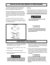
INSTALLATION AND BREAK-IN PROCEDURES
Location of the Air Compressor
Your compressor comes to you completely assembled
and ready for use. Operate the air compressor in a dry,
clean, cool and well ventilated area. The air compressor
pump and case are designed to allow for proper cooling.
Clean or blow off dust or dirt that collects on the air
compressor. A clean air compressor runs cooler and
provides longer service. The ventilation openings on your
air compressor are necessary to maintain proper operat-
ing temperature. Do not place rags or other containers on
or near these openings.
Extension Cords
Use extra air hose instead of an extension cord to avoid
voltage drop and power loss to the motor.
If an extension cord must be used, be sure it is:
• a 3-wire extension cord that has a 3-blade grounding
plug, and a 3-slot receptacle that will accept the plug on
the compressor
• in good condition
• no longer than 50 feet
• 14 gauge (AWG) or larger. (Wire size increases as gauge
number decreases.) 12 AWG, 10 AWG and 8 AWG may
also be used. DO NOT USE 16 OR 18 AWG.
ALWAYS SET THE PRESSURE VALVE AT OR
BELOW THE REQUIRED PRESSURE FOR THE
ACCESSORY BEING USED BEFORE START-
ING YOUR COMPRESSOR. FOR INFLATION
OR OTHER USES REQUIRING ACCURATE
PRESSURE, USE A PRESSURE GAUGE.
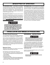
GROUNDING INSTRUCTIONS
RISK OF ELECTRICAL SHOCK! In the event of a
short circuit, grounding reduces the risk of shock by
providing an escape wire for the electric current.
This air compressor must be properly grounded.
The air compressor is equipped with a cord having a
grounding wire with an appropriate grounding plug.
The plug must be used with an outlet that has been
installed and grounded in accordance with all local
codes and ordinances. The outlet must have the same
configuration as the plug. See illustration. DO NOT
USE AN ADAPTER.
Inspect the plug and cord before each use. Do not use if
there are signs of damage.
IMPROPER GROUNDING CAN RESULT IN ELEC-
TRICAL SHOCK.