


7 — ENG
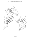
DESCRIPTION OF OPERATION
Air Compressor Pump: To compress air, the piston
moves up and down in the cylinder. On the downstroke, air
is drawn in through the intake valves. The exhaust valves
remain closed. On the upstroke of the piston, air is
compressed. The intake valves close and compressed air
is forced out through the exhaust valves, through the outlet
tube, through the check valve and into the air tank. Working
air is not available until the compressor has raised the tank
pressure above that required at the air outlet.
Check Valve: When the air compressor is operating, the
check valve is “open”, allowing compressed air to enter the
air tank. When the air compressor reaches “cut-out”
pressure, the check valve “closes”, allowing air pressure to
remain inside the air tank.
Pressure Switch: The pressure switch automatically
starts the motor when the tank pressure drops below the
factory set “cut-in” pressure. It stops the motor when the
air tank pressure reaches the factory set “cut-out” pressure.
Regulator: The air pressure coming from the air tank is
controlled by the regulator. Turn the regulator knob clock-
wise to increase pressure and counterclockwise to
decrease pressure. To avoid minor readjustment after
making a change in pressure setting, always approach the
desired pressure from a lower pressure. When reducing
from a higher to a lower setting, first reduce to pressure less
See front cover.
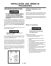
Extension Cords
Use extra air hose instead of an extension cord to avoid
voltage drop and power loss to the motor.
If an extension cord must be used, be sure it is:
• a 3-wire extension cord that has a 3-blade ground-
ing plug, and a 3-slot receptacle that will accept the
plug on the compressor.
• in good condition.
• no longer than 50 feet.
• 14 gauge (AWG) or larger. (Wire size increases as
gauge number decreases.) 12 AWG, 10 AWG and
8 AWG may also be used. DO NOT USE 16 OR 18
AWG.
Location of the Air Compressor
Your compressor comes to you completely assembled
and ready for use. Operate the air compressor in a dry,
clean, cool and well ventilated area. The air compressor
pump and case are designed to allow for proper cooling.
Clean or blow off dust or dirt that collects on the air
compressor. A clean air compressor runs cooler and
provides longer service. The ventilation openings on your
air compressor are necessary to maintain proper operating
temperature. Do not place rags or other containers on or
near these openings.
Voltage and Circuit Protection
than that desired, then bring it up to the desired pressure.
Depending on the air requirements of each particular
accessory, the outlet regulated air pressure may have to be
adjusted while operating the accessory.
Outlet Pressure Gauge: The outlet pressure gauge
indicates the air pressure available at the outlet side of the
regulator. This pressure is controlled by the regulator and
is always less or equal to the tank pressure. See “Operat-
ing Procedures”.
Tank Pressure Gauge: The tank pressure gauge indi-
cates the reserve air pressure in the tank.
Cooling System: This compressor contains an advanced
design cooling system. At the heart of this cooling system
is an engineered fan. It is perfectly normal for this fan to blow
air through the vent holes in large amounts. You know that
the cooling system is working when air is being expelled.
Air Intake Filter: This unit requires no air filter due to the
unique design of the air intake system.
Drain Valve: The drain valve is located at the base of the
air tank and is used to drain condensation at the end of each
use.
INSTALLATION AND BREAK-IN PROCEDURES