


17
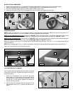
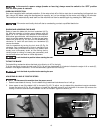
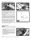
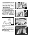
Insert the miter gauge bar into the miter gauge slot. Attach the
washer and lock handle (A) Fig. 42.
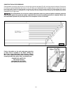
The miter gauge is equipped with adjustable index stops at
90° and 45° right and left. You can adjust the index stops by
tightening or loosening the three adjusting screws (B) Fig. 42
with the supplied hex wrench.
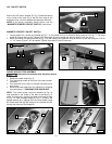
To rotate the miter gauge, loosen the lock knob (A) Fig. 42,
flip the stop link (D) out of the way, and move the body of the
miter gauge (C).
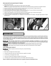
The miter gauge body (C) can stop at 90° and 45° both right
and left by flipping the stop link out of the way and moving the
miter gauge body (C) past the 90° and 45° marks and flipping
the stop link (D) back up so that the stop link (D) will be able
to contact the adjusting screws (B). To rotate the miter gauge
body past these points, flip the stop link (D) Fig. 43 out of the
way.
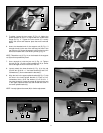
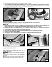
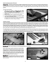
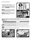
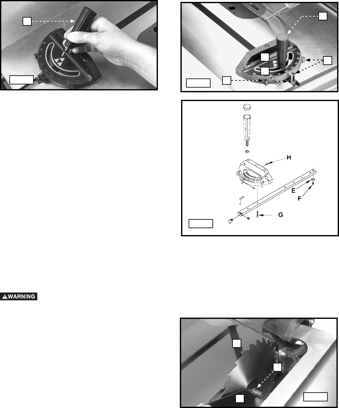
The head of the miter gauge pivots on a special tapered screw
(G) that fastens the head to the miter gauge bar. If the miter
gauge head does not pivot freely, or pivots too freely, adjust it
by loosening the set screw (H) Fig. 44, and turning the screw
(G) in or out. Tighten the screw (H) after adjustment.
Your miter gauge is equipped with a plate (E) Fig. 44 that fits
into the T-Slot groove in the table. This allows the miter gauge to be pulled away from the table without falling, allowing for a
longer cut-off capacity in front of the blade.
MITER GAUGE OPERATION AND ADJUSTMENT
NOTE: Use only 10" saw blades with 5/8" arbor holes, rated for at least 4000 RPM.
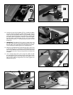
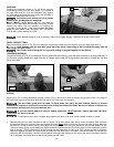
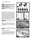
CHANGING THE SAW BLADE
Disconnect the machine from the power source!
NOTE: A 7/8” box-end wrench and a 7/8" open-end wrench are are supplied for changing the saw blade.
1. Remove the table insert and raise the saw blade to its
maximum height.
2. Place the open end wrench (B) Fig. 45 on the flats of the
saw arbor. Use the box end wrench (A) to turn the arbor
nut (C) toward the front of the saw. Remove the arbor nut,
blade flange and saw blade.
3. Install the new blade with the teeth pointing down at the
front of the saw table. Attach the outside blade flange and
arbor nut. With the wrench (B) Fig. 45 on the flats of the
arbor, tighten the arbor nut by turning the box end wrench
(A) toward the rear of the saw.
4. Replace the table insert.
Fig. 42
Fig. 43
Fig. 44
Fig. 45
A
A
C
B
B
D
B
A
C