


Belt Hook and Bit Clip (Fig. 1)
WARNING: To reduce the risk of serious personal injury, turn tool off and disconnect
battery pack before making any adjustments or removing/installing attachments or
accessories.
WARNING: To reduce the risk of serious personal injury, DO NOT suspend tool overhead
or suspend objects from the belt hook. ONLY hang tool’s belt hook from a work belt.
WARNING: To reduce the risk of serious personal injury, ensure the screw holding the belt
hook is secure.
IMPORTANT: When attaching or replacing the belt hook or bit clip, use only the screw (H) that is
provided. Be sure to securely tighten the screw.
The belt hook (G) and bit clip (I) can be be attached to either side of the tool using only the screw
(H) provided, to accommodate left- or right- handed users. If the hook or bit clip is not desired at
all, it can be removed from the tool.
To move belt hook or bit clip, remove the screw (H) that holds it in place then reassemble on the
opposite side. Be sure to securely tighten the screw.
OPERATION
WARNING: To reduce the risk of serious personal injury, turn tool off and disconnect
tool from power source before making any adjustments or removing/installing
attachments or accessories.
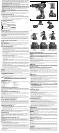
Installing and Removing the Battery Pack (Fig. 2)
NOTE: For best results, make sure your battery pack is fully charged.
To install the battery pack (K) into the tool handle, align the battery pack with the rails inside the
tool’s handle and slide it into the handle until the battery pack is firmly seated in the tool and ensure
that it does not disengage.
To remove the battery pack from the tool, press the release button (J) and firmly pull the battery
pack out of the tool handle. Insert it into the charger as described in the charger section of this
manual.
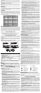
Drilling (Fig. 7)
NOTICE: If drilling thin material, use a wood “back-up” block to prevent damage to the material.
1. Select the desired speed/torque range using the gear shifter to match the speed and torque to
the planned operation. Turn the collar (C) to the drill symbol.
2. Use sharp drill bits only. For MASONRY, such as brick, cement, cinder block, etc., use carbide-
tipped bits rated for percussion drilling.
3. Always apply pressure in a straight line with the bit. Use enough pressure to keep drill biting,
but do not push hard enough to stall the motor or deflect the bit.
4. Hold tool firmly with both hands to control the twisting action of the drill. If model is not equipped
with side handle, grip drill with one hand on the handle and one hand on the battery pack.
WARNING: Drill may stall if overloaded causing a sudden twist. Always expect the stall. Grip the
drill firmly to control the twisting action and avoid injury.
5. IF DRILL STALLS, it is usually because it is being overloaded or improperly used. RELEASE
TRIGGER IMMEDIATELY, remove drill bit from work, and determine cause of stalling. DO
NOT DEPRESS TRIGGER ON AND OFF IN AN ATTEMPT TO START A STALLED DRILL
— THIS CAN DAMAGE THE DRILL.
6. To minimize stalling or breaking through the material, reduce pressure on drill and ease the bit
through the last fractional part of the hole.
7
. Keep the motor running when pulling the bit back out of a drilled hole. This will help prevent
jamming.
Screwdriving (Fig. 8)
1. Select the desired speed/torque range using the gear shifter to match the speed and torque to
the planned operation.
2. Turn the torque adjustment collar (C) to the desired position.
NOTE: Use the lowest torque setting required to seat the fastener at the desired depth. The
lower the number, the lower the torque output.
3. Insert the desired fastener accessory into the chuck as you would any drill bit.
4. Make some practice runs in scrap or on unseen areas of the workpiece to determine the proper
position of the torque adjustment collar.
5. Always start with lower torque settings, then advance to higher torque settings to avoid
damage to the workpiece or fastener.
Hammerdrilling (Fig. 9)
1. Select the desired speed/torque range using the gear shifter to match the speed and torque to
the planned operation. Turn the collar (C) to the hammerdrill symbol.
IMPORTANT: Use carbide-tipped or masonry bits rated for percussion drilling only.
2. Drill with just enough force on the hammer to keep it from bouncing excessively or "rising" off
the bit. Too much force will cause slower drilling speeds, overheating, and a lower drilling rate.
3. Drill straight, keeping the bit at a right angle to the work. Do not exert side pressure on the bit
when drillling as this will cause clogging of the bit flutes and a slower drilling speed.
4. When drilling deep holes, if the hammer speed starts to drop off, pull the bit partially out of the
hole with tool still running to help clear debris from the hole.
NOTE: A smooth, even flow of dust from the hole indicates proper drilling rate.
MAINTENANCE
WARNING: To reduce the risk of serious personal injury, turn tool off and disconnect
tool from power source before making any adjustments or removing/installing
attachments or accessories.
Cleaning
WARNING: Blow dirt and dust out of all air vents with dry air at least once a week. Wear proper
ANSI Z87.1 (CAN/CSA Z94.3) eye protection and proper NIOSH/OSHA/MSHA respiratory
protection when performing this.
WARNING: Never use solvents or other harsh chemicals for cleaning the non-metallic parts of
the tool. These chemicals may weaken the plastic materials used in these parts. Use a cloth
dampened only with water and mild soap. Never let any liquid get inside the tool; never immerse
any part of the tool into a liquid.
CHARGER CLEANING INSTRUCTIONS
WARNING: Shock hazard. Disconnect the charger from the AC outlet before cleaning. Dirt and
grease may be removed from the exterior of the charger using a cloth or soft non-metallic brush.
Do not use water or any cleaning solutions.
Repairs
The charger and battery pack are not serviceable. There are no serviceable parts inside the charger
or battery pack.
To assure product SAFETY and RELIABILITY, repairs, maintenance and adjustments (including
brush inspection and replacement) should be performed by a D
EWALT factory service center,
a D
EWALT authorized service center or other qualified service personnel. Always use identical
replacement parts.
Accessories
WARNING: Since accessories, other than those offered by DEWALT, have not been tested with
this product, use of such accessories with this tool could be hazardous. To reduce the risk of injury,
only D
EWALT recommended accessories should be used with this product.
Recommended accessories for use with your tool are available at extra cost from your local dealer
or authorized service center. If you need assistance in locating any accessory, please contact
• Do not place any object on top of the charger or place the charger on a soft surface
that might block the ventilation slots and result in excessive internal heat. Place the
charger in a position away from any heat source. The charger is ventilated through slots in the
top and the bottom of the housing.
• Do not operate the charger with a damaged cord or plug.
• Do not operate the charger if it has received a sharp blow, been dropped or otherwise
damaged in any way. Take it to an authorized service center.
• Do not disassemble the charger; take it to an authorized service center when service or
repair is required. Incorrect reassembly may result in a risk of electric shock, electrocution or fire.
• Disconnect the charger from the outlet before attempting any cleaning. This will
reduce the risk of electric shock. Removing the battery pack will not reduce this risk.
• NEVER attempt to connect 2 chargers together.
• The charger is designed to operate on standard 120V household electrical power. Do
not attempt to use it on any other voltage. This does not apply to the vehicular charger.
Chargers
Your tool uses a DEWALT charger. Be sure to read all safety instructions before using your charger.
Consult the chart at the end of this manual for compatibility of chargers and battery packs.
Charging Procedure (Fig. 3)
1. Plug the charger into an appropriate outlet before inserting the battery pack.
2. Insert the battery pack (K) into the charger, as shown in Figure 3, making sure the pack is fully
seated in charger. The red (charging) light will blink continuously, indicating that the charging
process has started.
3. The completion of charge will be indicated by the red light remaining ON continuously. The pack
is fully charged and may be used at this time or left in the charger.
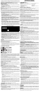
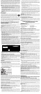
Indicator Light Operation
PACK CHARGING
PACK CHARGED
x
HOT/COLD DELAY
PROBLEM PACK OR CHARGER
PROBLEM POWERLINE
Charge Indicators
This charger is designed to detect certain problems that can arise. Problems are indicated by the red
light flashing at a fast rate. If this occurs, re-insert the battery pack into the charger. If the problem
persists, try a different battery pack to determine if the charger is working properly. If the new pack
charges correctly, then the original pack is defective and should be returned to a service center or
other collection site for recycling. If the new battery pack elicits the same trouble indication as the
original, have the charger and the battery pack tested at an authorized service center.
HOT/COLD DELAY
This charger has a hot/cold delay feature: when the charger detects a battery that is hot, it
automatically starts a delay, suspending charging until the battery has cooled. After the battery
has cooled, the charger automatically switches to the pack charging mode. This feature ensures
maximum battery life. The red light flashes long, then short while in the hot/cold delay mode.
LEAVING THE BATTERY PACK IN THE CHARGER
The charger and battery pack can be left connected with the charge indicator showing Pack
Charged.
WEAK BATTERY PACKS: Weak batteries will continue to function but should not be expected to
perform as much work.
FAULTY BATTERY PACKS: This charger will not charge a faulty battery pack. The charger will
indicate faulty battery pack by refusing to light or by displaying problem pack or charger.
NOTE: This could also mean a problem with a charger.
Important Charging Notes
1. Longest life and best performance can be obtained if the battery pack is charged when the air
temperature is between 65°F and 75°F (18° – 24°C). DO NOT charge the battery pack in an
air temperature below +40°F (+4.5°C), or above +105°F (+40.5°C). This is important and will
prevent serious damage to the battery pack.
2. The charger and battery pack may become warm to the touch while charging. This is a normal
condition, and does not indicate a problem. To facilitate the cooling of the battery pack after
use, avoid placing the charger or battery pack in a warm environment such as in a metal shed
or an uninsulated trailer.
3. A cold battery pack will charge at about half the rate of a warm battery pack. The battery
pack will charge at that slower rate throughout the entire charging cycle and will not return to
maximum charge rate even if the battery pack warms.
4. If the battery pack does not charge properly:
a. Check operation of receptacle by plugging in a lamp or other appliance;
b. Check to see if receptacle is connected to a light switch which turns power off when you turn
out the lights;
c. Move the charger and battery pack to a location where the surrounding air temperature is
approximately 65°F – 75°F (18° – 24°C);
d. If charging problems persist, take the tool, battery pack and charger to your local service
center.
5. The battery pack should be recharged when it fails to produce sufficient power on jobs which
were easily done previously. DO NOT CONTINUE to use under these conditions. Follow the
charging procedure. You may also charge a partially used pack whenever you desire with no
adverse effect on the battery pack.
6. Foreign materials of a conductive nature such as, but not limited to, grinding dust, metal chips,
steel wool, aluminum foil, or any buildup of metallic particles should be kept away from charger
cavities. Always unplug the charger from the power supply when there is no battery pack in the
cavity. Unplug the charger before attempting to clean.
7. Do not freeze or immerse the charger in water or any other liquid.
WARNING: Shock hazard. Don’t allow any liquid to get inside the charger. Electric shock may
result.
WARNING: Burn hazard. Do not submerge the battery pack in any liquid or allow any liquid to
enter the battery pack. Never attempt to open the battery pack for any reason. If the plastic housing
of the battery pack breaks or cracks, return to a service center for recycling.
Storage Recommendations
1. The best storage place is one that is cool and dry, away from direct sunlight and excess heat
or cold.
2. For long storage, it is recommended to store a fully charged battery pack in a cool dry place
out of the charger for optimal results.
NOTE: Battery packs should not be stored completely depleted of charge. The battery pack will
need to be recharged before use.
SAVE THESE INSTRUCTIONS FOR FUTURE USE
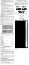
COMPONENTS (Fig. 1)
WARNING: Never modify the power tool or any part of it. Damage or personal injury could result.
A. Trigger switch G. Belt hook
B. Forward/reverse control button H. Mounting screw
C. Torque adjustment collar I. Bit clip
D. Gear shifter J. Battery release button
E. Worklight K. Battery pack
F. Keyless chuck
Variable Speed Trigger Switch (Fig. 1)
To turn the tool on, squeeze the trigger switch (A). To turn the tool off, release the trigger switch.
Your tool is equipped with a brake. The chuck will stop as soon as the trigger switch is fully released.
NOTE: Continuous use in variable speed range is not recommended. It may damage the switch
and should be avoided.
Forward/Reverse Control Button (Fig. 1)
A forward/reverse control button (B) determines the direction of the tool and also serves as a
lock-off button.
To select forward rotation, release the trigger switch and depress the forward/reverse control
button on the right side of the tool.
To select reverse, depress the forward/reverse control button on the left side of the tool.
The center position of the control button locks the tool in the off position. When changing the
position of the control button, be sure the trigger is released.
NOTE: The first time the tool is run after changing the direction of rotation, you may hear a click on
start up. This is normal and does not indicate a problem.
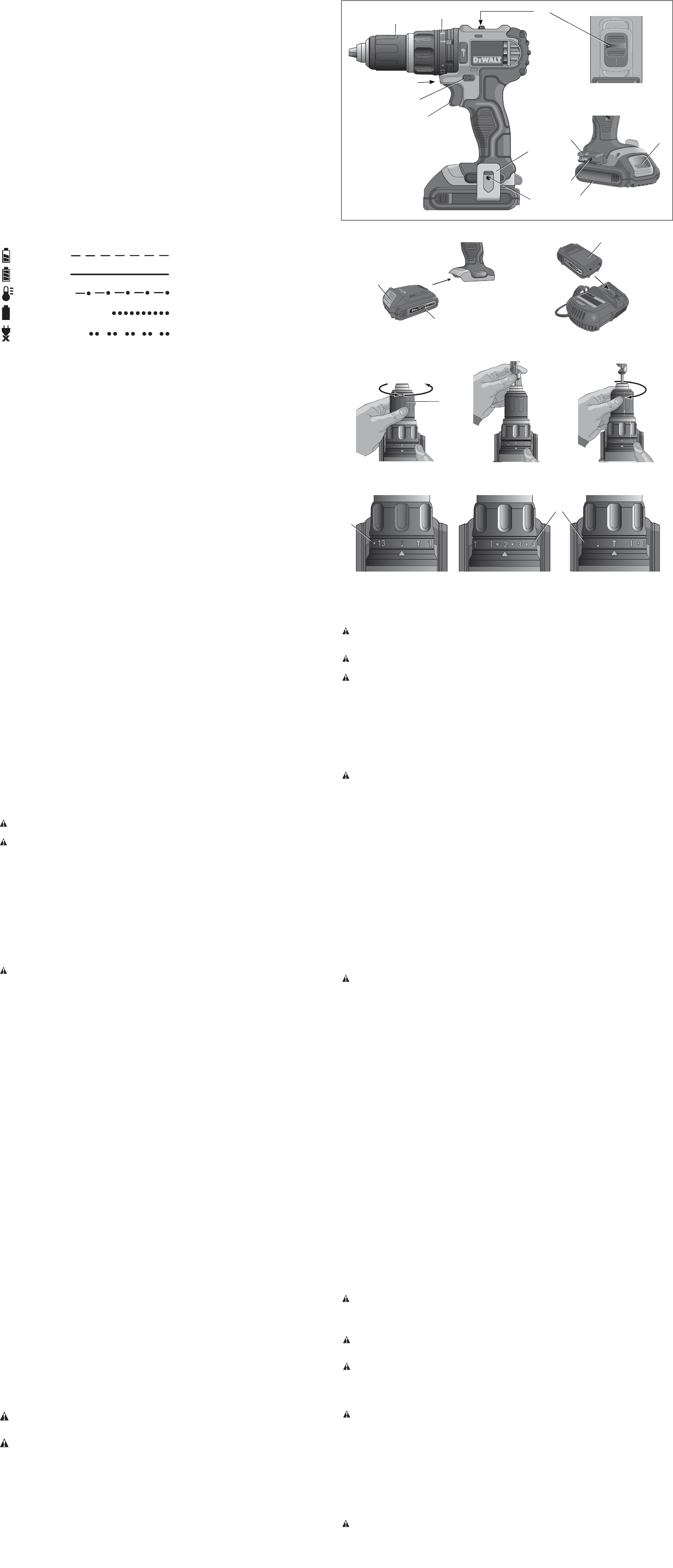
Torque Adjustment Collar (Fig. 1)
Your tool has an adjustable torque screwdriver mechanism for driving and removing a wide array
of fastener shapes and sizes and in some models, a hammer mechanism for drilling into masonry.
Circling the collar (C) are numbers, a drill bit symbol, and in some models, a hammer symbol. These
numbers are used to set the clutch to deliver a torque range. The higher the number on the collar,
the higher the torque and the larger the fastener which can be driven. To select any of the numbers,
rotate until the desired number aligns with the arrow.
Dual Range Gearing (Fig. 1)
The dual range feature of your drill/driver allows you to shift gears for greater versatility.
1. To select speed 1 (high torque setting), turn the tool off and permit it to stop. Slide the gear
shifter (D) forward (towards the chuck).
2. To select speed 2 (low torque setting), turn the tool off and permit it to stop. Slide the gear
shifter back (away from the chuck).
NOTE: Do not change gears when the tool is running. Always allow the drill to come to a complete
stop before changing gears. If you are having trouble changing gears, make sure that the dual range
gear shifter is either completely pushed forward or completely pushed back.
Worklight (Fig. 1)
There is a worklight (E) located just above the trigger switch (A). The worklight is activated when
the trigger switch is depressed, and will automatically turn off 20 seconds after the trigger switch is
released. If the trigger switch remains depressed, the worklight will remain on.
NOTE: The worklight is for lighting the immediate work surface and is not intended to be used as
a flashlight.
Keyless Single Sleeve Chuck (Fig. 4–6)
WARNING: Do not attempt to tighten drill bits (or any other accessory) by gripping the front part
of the chuck and turning the tool on. Damage to the chuck and personal injury may result. Always
lock off trigger switch and disconnect tool from power source when changing acces sories.
WARNING: Always ensure the bit is secure before starting the tool. A loose bit may eject from
tool causing possible personal injury.
Your tool features a keyless chuck (F) with one rotating sleeve for one-handed operation of the
chuck. To insert a drill bit or other accessory, follow these steps.
1. Turn tool off and disconnect tool from power source.
2. Grasp the black sleeve of the chuck with one hand and use the other hand to secure the
tool. Rotate the sleeve counterclockwise far enough to accept the desired accessory.
3. Insert the accessory about 3/4" (19 mm) into the chuck and tighten securely by rotating
the chuck sleeve clockwise with one hand while holding the tool with the other. Your tool is
equipped with an automatic spindle lock mechanism. This allows you to open and close the
chuck with one hand.
Be sure to tighten chuck with one hand on the chuck sleeve and one hand holding the tool for
maximum tightness.
To release the accessory, repeat steps 1 and 2 above.
FIG. 7
HAMMERDRILLING
PERFORATION PAR PERCUSSION
TALADRADO PERCUTOR
FIG. 9
SCREWDRIVING
VISSAGE
DESTORNILLADO
FIG. 8
DRILLING
PERÇAGE
TALADRADO
C
C
FIG. 3
K
FIG. 2
K
J
A
B
C
FIG. 1
D
F
E
G
H
I
J
K
H
FIG. 5
FIG. 6
F
FIG. 4