


8. Place the toggle switch in the on position. This allows the trigger switch on the D-handle
to control the router.
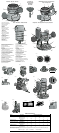
Locking Lever Adjustment (Fig. 4)
CAUTION: Turn the router off and disconnect it from the power supply.
You should be able to clamp the locking lever without excessive force. Excessive force may
damage the base.
You should not be able to move the motor in the base when the locking lever is clamped. To
adjust the locking lever’s clamping force, open the locking lever (D) and turn the nut (Y) in
small increments. Turning the nut clockwise tightens the lever while turning the nut counter-
clockwise loosens the lever.
Centering the Subbase (Fig. 5)
CAUTION: Turn the router off and disconnect it from the power supply.
If you need to adjust, change, or replace the subbase, a centering tool is provided. The cen-
tering tool consists of a cone and a pin. To adjust the subbase, follow the steps below.
1. Loosen but do not remove the subbase screws so that the subbase can move freely.
2. Insert the pin into the collet and tighten the collet nut.
3. Insert the motor into the base and clamp the locking lever on the base.
4. Place the cone on the pin and lightly press down on cone until it stops as shown. This will
center the subbase.
5. While holding down on the cone, tighten the subbase screws.
OPERATION: D-HANDLE BASE
Knob Locations
Grip the D-Handle with one hand and place the other hand on the the knob. The D-Handle
router base has two positions for the knob to accommodate right or left hand use.
CAUTION: Use both hands at all times to maintain control.
Trigger Lock
To lock the trigger, pull the trigger switch (N) completely, then push the trigger lock button (O).
The router will remain on after you remove your finger from the trigger. To unlock the trigger lock
button, pull the trigger and release. The lock button will pop out and the router will turn off.
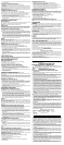
Bit Installation and Removal (Fig. 6)
CAUTION: Turn the router off and disconnect it from the power supply.
1. To install a bit, insert the round shank of the desired router bit into the loosened collet as far
as it will go and then pull it out about 1/16". Using the wrench(es) provided, turn the collet
nut (J) clockwise while holding the spindle shaft with the second wrench. [On the DW618,
depress the spindle lock button (I) to hold the spindle shaft.]
2. To remove a bit, hold the spindle shaft while turning the collet nut (J) counterclockwise with
the wrench provided. [Hold the spindle by depressing the spindle lock button (I) on the
DW618.] The self-releasing collet nut will turn approximately 3/4 of a turn and then become
tight again. At this point the bit cannot be removed. Continue turning the collet nut counter-
clockwise. This lifts the collet, allowing the bit’s removal.
Collets
NOTE: Never tighten the collet without first installing a router bit in it. Tightening an empty col-
let, even by hand, can damage the collet.
Two collets are included with the motor: one 1/4" and one 1/2". To change collet sizes, unscrew
the collet assembly as described above. Install the desired collet by reversing the
procedure.The collet and the collet nut are connected. Do not attempt to remove the collet from
the collet nut.
Adjusting the Depth of Cut (Fig. 3)
CAUTION: Turn the router off and disconnect it from the power supply.
1. Select and install the desired bit. See the heading Bit Installation and Removal.
2. Place the router on its base on the work piece.
3. Open the locking lever (D) and turn the depth adjustment ring (B) until the bit just touches
the work piece. Turning the ring clockwise raises the cutting head while turning it counter-
clockwise lowers the cutting head.
4. Move the adjustable scale clockwise so that 0 on the scale is located exactly above the
pointer (Z) on the base.
5. Turn the depth adjustment ring along with the adjustable scale to the desired depth. Note
that each mark on the adjustable scale represents a depth change of 1/64" or .015"
(.4mm).
6. Close the locking lever (D).
Using a Parallel Fence
A parallel fence (DW6913) is available from your local retailer or service center at extra cost.
Follow the assembly instructions included with the fence. Insert the two bars through the holes
in the router base. Adjust as needed for parallel routing.
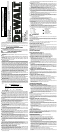
SET-UP: PLUNGE BASE (Fig. 8)
Motor Quick Release
CAUTION: Turn the router off and disconnect it from the power supply.
1. Open the locking lever (D) on the base.
2. Grasp the top of the motor unit and lift it from the base.
Inserting the Motor into the Plunge Base
CAUTION: Turn the router off and disconnect it from the power supply.
1. Remove the depth adjustment ring from the motor. It is not used with the plunge base.
2. Open the locking lever (D) on the base to ensure that the motor properly seats.
3. Ensure that the plunge lock lever (R) is locked.
4. Align the flat of the motor’s end cap (BB) with pillar (CC) and insert the motor into the
plunge base until it stops.
5. Close the locking lever (D).
Locking Lever Adjustment (Fig. 4)
CAUTION: Turn the router off and disconnect it from the power supply.
You should be able to clamp the locking lever without excessive force. Excessive force may
damage the base.
You should not be able to move the motor in the base when the locking lever is clamped.
To adjust the locking lever’s clamping force, open the locking lever (D) and turn the nut
(Y) in small increments. Turning the nut clockwise tightens the lever, while turning the nut
counterclockwise loosens the lever.
Centering the Subbase (Fig. 5)
CAUTION: Turn the router off and disconnect it from the power supply.
If you need to adjust, change, or replace the subbase, a centering tool is provided. The
centering tool consists of a cone and a pin. To adjust the subbase, follow the steps below.
1. Loosen but do not remove the subbase screws so that the subbase can move freely.
2. Insert the pin into the collet and tighten the collet nut.
3. Insert the motor into the base and clamp the locking lever on the base.
4. Place the cone on the pin and lightly press down on the cone until it stops as shown. This
will center the subbase.
5. While holding down on the cone, tighten the subbase screws.
OPERATION: PLUNGE BASE
Bit Installation and Removal (Fig. 6)
CAUTION: Turn the router off and disconnect it from the power supply.
1. To install a bit, insert the round shank of the desired router bit into the loosened collet as
far as it will go and then pull it out about 1/16". Using the wrench(es) provided, turn the col-
let nut (J) clockwise while holding the spindle shaft with the second wrench. [On the
DW618, depress the spindle lock button (I) to hold the spindle shaft.]
2. To remove a bit, hold the spindle shaft while turning the collet nut (J) counterclockwise
with the wrench provided. [Hold the spindle by depressing the spindle lock button (I) on
the DW618.] The self-releasing collet nut will turn approximately 3/4 of a turn and then
become tight again. At this point the bit cannot be removed. Continue turning the collet
nut counterclockwise. This lifts the collet, allowing the bit’s removal.
Collets
NOTE: Never tighten the collet without first installing a router bit in it. Tightening an empty col-
let, even by hand, can damage the collet.
Two collets are included with the motor: one 1/4" and one 1/2". To change collet sizes, unscrew
the collet assembly as described above. Install the desired collet by reversing the
procedure.The collet and the collet nut are connected. Do not attempt to remove the collet from
the collet nut.
Adjusting the Plunge Routing Depth (Fig. 8)
CAUTION: Turn the router off and disconnect it from the power supply.
1. Unlock the plunge mechanism by pushing up the plunge lock lever (R). Plunge the router
down as far as it will go, allowing the bit to just touch the workpiece.
2. Lock the plunge mechanism by pushing the plunge lock lever (R) down.
3. Loosen the depth adjustment rod (Q) by turning the wingscrew (DD) counterclockwise.
4. Slide the depth adjustment rod (Q) down so that it meets the lowest turret stop (P).
5. Slide the tab (EE) on the depth adjustment rod down so that the top of it meets zero on the
pillar scale (FF).
6. Grasping the top, knurled section of the depth adjustment rod (Q), slide it up so that the
tab (EE) aligns with the desired depth of cut on the pillar scale (FF).
7. Tighten the wingscrew (DD) to hold the depth adjustment rod in place.
8. Keeping both hands on the handles, unlock the plunge mechanism by pushing the plunge
lock lever (R) up. The plunge mechanism and the motor will move up. When the router is
plunged, the depth adjustment rod will hit the turet stop, allowing the router to reach exact-
ly the desired depth.
Fine Adjustment of Routing Depth
CAUTION: Turn the router off and disconnect it from the power supply.
The knurled knob (GG) at the bottom end of the depth adjustment rod can be used to make
minor adjustments.
1. To decrease the cutting depth, rotate the knob clockwise (looking down from the top of the
router).
2. To increase the cutting depth, rotate the knob counterclockwise (looking down from the top
of the router).
NOTE: One complete rotation of the knob results in a change of about 5/128" or .04" (1 mm)
in depth.
Using the Rotating Turret Stop (Fig. 9)
The turret depth stop can be used to set 5 different depths. One of the turret stops is adjustable.
To use the adjustable turret stop, loosen the nut (HH), then adjust the screw (II) to the desired
height. Turning the screw counterclockwise will raise the screw which will decrease the cutting
depth. The turret stop is useful for making deep cuts in several passes.
WARNING: Do not change the turret stop while the router is running. This will place your
hands too near the cutter head.
Cutting with the Plunge Base (Fig. 8)
CAUTION: Turn the router on before plunging the cutter head into the workpiece.
1. Unlock the plunge lock lever (R).
2. Plunge the router down until the bit reaches the set depth.
3. Lock the plunge lock lever (R).
4. Perform the cut.
5. Unlock the plunge lock lever. This will allow the router bit to disengage the work.
6. Turn the router off.
Dust Extraction (Fig. 10)
CAUTION: Turn the router off and disconnect it from the power supply.
To connect the router to a vacuum cleaner for dust extraction, follow these steps:
1. Remove the dust cap (T) by pulling straight up.
2. Insert the dust extraction hose adapter (JJ) into the dust extraction port (KK) as shown.
3. Insert the end of a standard vacuum cleaner tube (LL) into the hose adapter.
4. When using dust extraction, be aware of the placement of the vacuum cleaner. Be sure that
the vacuum cleaner is stable and that its hose will not interfere with the work.
OPERATION: ALL BASES
Direction Of Feed (Fig. 11)
The direction of feed is very important when routing and can make the difference between a
successful job and a ruined project. The figures at left show the proper direction of feed for
some typical cuts. A general rule to follow is to move the router in a counterclockwise direction
on an outside cut and a clockwise direction on an inside cut.
Shape the outside edge of a piece of stock by following these steps:
1. Shape the end grain, left to right
2. Shape the straight grain side moving left to right
3. Cut the other end grain side
4. Finish the remaining straight grain edge
Choosing Router Speed (DW618 only) (Fig. 12)
Refer to the chart above to choose a router speed. Turn the speed dial (G) to control router
speed.
MAINTENANCE
Cleaning
WARNING: Blowing dust and chips out of the motor housing using clean, dry compressed
air is a necessary regular maintenance procedure. Dust and chips containing metal particles
often accumulate on interior surfaces and could create an electrical shock or electrocution if
not frequently cleaned out. ALWAYS WEAR SAFETY GLASSES.
CAUTION: Never use solvents or other harsh chemicals for cleaning the non-metallic parts
of the tool. Use a clean, dry rag only.
NOTE FOR PLUNGE BASE ONLY: Use only a DRY cloth to wipe the plunge rods. These
rods require no lubrication. Lubricants attract dust, reducing the performance of your tool.
Accessories
Recommended accessories for use with your tool are available at extra cost from your local
dealer or authorized service center. If you need assistance in locating any accessory for your
tool, call us toll free at: 1-800-4-D
EWALT (1-800-433-9258) or contact DEWALT Industrial Tool
Co., 701 East Joppa Road, Baltimore, MD 21286.
CAUTION: The use of any other accessory not recommended for use with this tool could
be hazardous.
Repairs
To assure product SAFETY and RELIABILITY, repairs, maintenance and adjustment (includ-
ing brush inspection and replacement) should be performed by authorized service centers or
other qualified service personnel, always using identical replacement parts.
Three Year Limited Warranty
DEWALT will repair, without charge, any defects due to faulty materials or workmanship for
three years from the date of purchase. This warranty does not cover part failure due to normal
wear or tool abuse. For further detail of warranty coverage and warranty repair information,
visit www.dewalt.com or call 1-800-4-D
EWALT (1-800-433-9258). This warranty does not apply
to accessories or damage caused where repairs have been made or attempted by others. This
warranty gives you specific legal rights and you may have other rights which vary in certain
states or provinces.
In addition to the warranty, D
EWALT tools are covered by our:
1 YEAR FREE SERVICE
DEWALT will maintain the tool and replace worn parts caused by normal use, for free, any time
during the first year after purchase.
90 DAY MONEY BACK GUARANTEE
If you are not completely satisfied with the performance of your D
EWALT Power Tool, Laser,
or Nailer for any reason, you can return it within 90 days from the date of purchase with a
receipt for a full refund – no questions asked.
RECONDITIONED PRODUCT: Reconditioned product is covered under the 1 Year Free
Service Warranty. The 90 Day Money Back Guarantee and the Three Year Limited Warranty
do not apply to reconditioned product.
FREE WARNING LABEL REPLACEMENT: If your warning labels become illegible or are
missing, call 1-800-4-D
EWALT for a free replacement.
SI VOUS AVEZ DES QUESTIONS OU VOUS VOULEZ NOUS FAIRE PART DE VOS COM-
MENTAIRES CONCERNANT CET OUTIL OU TOUT AUTRE OUTIL DEWALT, COMPOSEZ
SANS FRAIS LE 1 800 433-9258.
CONSERVER CES DIRECTIVES!
MESURES DE SÉCURITÉ – GÉNÉRALITÉS
AVERTISSEMENT! Lire et comprendre toutes les directives, car le non-
respect des directives suivantes pourrait entraîner un risque de choc élec-
trique, d’incendie ou de blessures graves.
CONSERVER CES DIRECTIVES
Consignes de sécurité concernant tous les outils
ZONE DE TRAVAIL
Garder la zone de travail propre et bien éclairée; les établis encombrés et les endroits
sombres sont propices aux accidents.
Ne pas utiliser les outils électriques dans une atmosphère explosive, comme à
proximité de liquides, de gaz ou de poussières inflammables; le moteur peut créer
des étincelles et enflammer les vapeurs ou les poussières environnantes.
Tenir les enfants, les visiteurs ou toute autre personne à l’écart lorsqu’on utilise un
outil électrique; les distractions peuvent faire perdre la maîtrise de ce dernier.
MESURES DE SÉCURITÉ - ÉLECTRICITÉ
Les outils mis à la terre doivent être branchés dans une prise bien installée et mise
à la terre conformément à tous les codes et règlements en vigueur. Ne jamais retir-
er la broche de terre ni modifier la fiche. Ne pas utiliser d'adaptateur. Vérifier auprès
d'un électricien qualifié en cas de doute quant à la mise à la terre de la prise. En cas
de défaillance électrique ou de bris de l'outil, la mise à la terre procure un chemin de faible
résistance au courant qui autrement traverserait l'utilisateur. Pour éviter que l’utilisateur ne
soit électrocuté en cas de défaillance, de bris ou de conductivité de l’outil, celui-ci est doté
d’une fiche à trois broches afin d’assurer la mise à la terre. Il y a risque d’électrocution, de
blessures graves ou de mort lorsqu’on utilise un outil dont une broche est endommagée ou
absente ou dont la fiche ou le cordon est endommagé ou qui n’est pas branché dans une
prise conforme mise continuellement à la terre. Pour éviter les risques de blessures, l’outil
doit toujours être bien entretenu et en bon état de marche (cordon, broches de la fiche)
et doit être branché dans une prise mise à la terre continuellement. (Voir également la
rubrique « Nettoyage » dans la section Entretien.)
Éviter tout contact entre le corps et les éléments mis à la terre, comme les tuyaux,
les radiateurs, les cuisinières et les réfrigérateurs, afin de réduire les risques de choc
électrique.
Ne pas utiliser l’outil électrique dans des endroits mouillés, ni l’exposer à la pluie;
l’infiltration d’eau à l’intérieur de l’outil augmente les risques de choc électrique.
Ne pas utiliser le cordon de manière abusive; on ne doit pas transporter l’outil en le
tenant par le cordon, ou utiliser ce dernier pour le débrancher. On doit tenir le cor-
don à l’écart des sources de chaleur, de l’huile, des bords tranchants ou des pièces
mobiles. Remplacer immédiatement les cordons endommagés, car ces derniers aug-
mentent les risques de choc électrique.
Lorsqu’on utilise un outil électrique à l’extérieur, on ne doit utiliser que des ral-
longes conçues pour cet usage, comme celles de type
«
W-A
»
ou
«
W
»
, afin de
réduire les risques de choc électrique.
RALLONGES
S’assurer que la rallonge est en bon état; si on utilise une rallonge, s’assurer d’en
choisir une qui est en mesure de porter le courant nécessaire à l’outil. Une baisse
de tension de plus de 10 p. 100 peut entraîner une perte de puissance et la surchauffe.
Une rallonge de calibre inférieur entraînera une chute de tension se traduisant par une
perte de puissance et une surchauffe. Le tableau ci-dessous illustre les calibres que l’on
doit utiliser selon la longueur de la rallonge et l’intensité nominale indiquée sur la plaque
signalétique. En cas de doute, utiliser le calibre suivant. Plus le calibre est petit, plus la ral-
longe peut porter de courant.
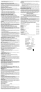
Calibre minimal des cordons de rallonge
TensionLongueur totale du cordon en meters
120 V De 0 à 7 De 7 à 15 De 15 à 30 De 30 à 45
240 V De 0 à 7 De 7 à 15 De 15 à 39 De 30 à 45
Intensité (A)
Au Au Calibre moyen de fil
moins plus
10 - 12 16 16 14 12
12 - 16 14 12 Non recommandé
SÉCURITÉ PERSONNELLE
Rester vigilant en tout temps et faire preuve de jugement lorsqu’on utilise un outil
électrique; ne pas utiliser l’outil lorsqu’on est fatigué ou sous l’influence de drogues,
d’alcool ou de médicaments, car un moment d’inattention pourrait entraîner des blessures
graves.
Porter des vêtements appropriés; ne pas porter de vêtements amples ni de bijoux.
Couvrir ou attacher les cheveux longs. Garder les cheveux, les vêtements, les bijoux
et les gants éloignés des pièces mobiles, car ceux-ci peuvent s’y coincer. Se tenir éloigné
des évents puisque ces derniers pourraient camoufler des pièces mobiles.
Éviter les démarrages accidentels; s’assurer que l’interrupteur est en position d’ar-
rêt avant de brancher l’outil. Ne pas transporter l’outil en laissant le doigt sur l’interrup-
teur ni le brancher lorsque l’interrupteur est en position de marche, car cela pourrait causer
un accident.
Retirer les clés de réglage avant de démarrer l’outil; une clé laissée sur une pièce rota-
tive peut entraîner des blessures.
Ne pas trop étendre les bras; les pieds doivent rester ancrés fermement au sol afin
de maintenir son équilibre en tout temps et de mieux maîtriser l’outil dans des situa-
tions imprévues.
Utiliser le matériel de sécurité approprié; toujours porter des lunettes de protection.
Porter un masque anti-poussières, des chaussures antidérapantes, un casque de sécurité
ou des protecteurs auditifs lorsque la situation le requiert.
UTILISATION ET ENTRETIEN DE L’OUTIL
Fixer et soutenir le matériel sur une plate-forme stable au moyen d’une bride de ser-
rage ou de tout autre dispositif semblable; le matériel est instable lorsqu’on le retient
manuellement ou qu’on l’appuie contre le corps, ce qui peut faire perdre la maîtrise de l’outil.
Ne pas forcer l’outil ni l’utiliser pour des travaux autres que ceux pour lesquels il a
été conçu. Pour obtenir de meilleurs résultats et prévenir les risques de blessure, laisser
l’outil couper à la vitesse pour laquelle il a été conçu.
Ne pas utiliser l’outil lorsque l’interrupteur marche-arrêt ne fonctionne pas; tout outil
qui ne peut être commandé au moyen de l’interrupteur est dangereux et doit être réparé.