


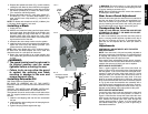
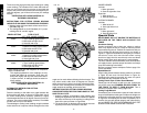
25 degrees. Figure V2 shows a setting of 24-1/4
degrees right miter.
For settings that require partial degrees (1/4, 1/2, 3/4
degrees) align the desired vernier mark with the CLOS-
EST degree mark on the miter scale, as described below
(The plastic vernier plate is inscribed with marks for 1/4,
1/2, 3/4 and 1 degrees. Only the 1/2 degree and the 1
degree are numerically labeled.)
WHEN MITERING TO THE RIGHT
To increase the miter angle when mitering to the right,
move the arm to align the appropriate vernier mark with the
closest mark on the miter scale to the right. To decrease
the miter angle when mitering to the right, move the arm to
align the appropriate vernier mark with the closest mark on
the miter scale to the left.
WHEN MITERING TO THE LEFT
To increase the miter angle when mitering to the left, move
the arm to align the appropriate vernier mark with the clos-
est mark on the miter scale to the left. To decrease the
miter angle when mitering to the left, move the arm to align
the appropriate vernier mark with the closest mark on the
miter scale to the right.
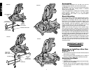
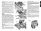
CUTTING BASE MOLDING
ALWAYS MAKE A DRY RUN WITHOUT POWER
BEFORE MAKING ANY CUTS.
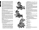
Straight 90 degree cuts :
Position the wood against the fence and clamp it in
place as shown in Figure 21. Turn on the saw, allow the
blade to reach full speed and lower the arm smoothly
through the cut.
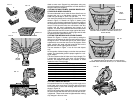
CUTTING BASE MOLDING UP TO 3-7/8" HIGH
VERTICALLY AGAINST THE FENCE
• Position molding as shown in Figure 22
• All cuts made with the back of the molding against the
fence and bottom of the molding against the base
INSIDE CORNER:
Left side
1. Miter left 45°
2. Save left side of cut
Right side
1. Miter Right 45°
2. Save right side of cut
OUTSIDE CORNER:
Left side
1. Miter right at 45°
2. Save left side of cut
Right side
1. Miter left at 45°
2. Save right side of cut
Material up to 3.9" (3-7/8)" can be cut as described above.
For wider boards [up to 5.5" (5-1/2")] several minor con-
cessions must be made.
English
10
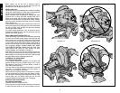
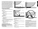
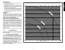
The chart shown on page 12 will assist you in selecting the
proper bevel and miter settings for common compound
miter cuts. To use the chart, select the desired angle “A”
(Figure 19) of your project and locate that angle on the
appropriate arc in the chart. From that point follow the
chart straight down to find the correct bevel angle and
straight across to find the correct miter angle.
Set your saw to the prescribed angles and make a few trial
cuts. Practice fitting the cut pieces together until you devel-
op a feel for this procedure and feel comfortable with it.
Example: To make a 4 sided box with 26° exterior angles
(Angle A, Figure 19), use the upper right arc. Find 26° on
the arc scale. Follow the horizontal intersecting line to
either side to get miter angle setting on saw (42°).
Likewise, follow the vertical intersecting line to the top or
bottom to get the bevel angle setting on the saw (18°).
Always try cuts on a few scrap pieces of wood to verify set-
tings on saw.
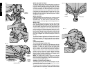
DUAL RANGE MITER SCALE
The miter scale has two ranges of numbers for conven-
ience, as shown in Figure 20. One scale indicates 0
degrees when the blade is square to the fence. At this
position the other scale reads 90 degrees.
The 0 degree scale (larger numbers closer to the front
edge) is used when calculating angles. To calculate the
proper miter angle, divide 180 degrees by the number of
sides of the box or frame. Refer to the chart on page 9 for
some examples.
The 90 degree scale (smaller numbers behind the zero
degree scale) is used when a corner of your box or frame
is measured with a protractor. For example: if you meas-
ure the corner of an 8 sided box, the protractor will read
135 degrees. To determine the proper miter setting, divide
the measured angle by two. The proper miter setting in this
example is 67-1/2 degrees. Set this angle on the 90
degree scale. This is most useful when a corner is at an
odd angle.
VERNIER SCALE (FIG. V1, V2)
Your saw is equipped with a vernier scale for added preci-
sion. The vernier scale allows you to accurately set miter
angles to the nearest 1/4 degree (15 minutes). To use the
vernier scale follow the steps listed below.
(As an example, let’s assume that the angle you want to
miter is 24 1/4 degree right).
1. Turn off miter saw.
2. Set the miter angle to the nearest whole degree
desired by aligning the center mark in the vernier
scale, shown in Figure V1, with the whole degree num-
ber etched in the miter scale. Examine Figure V2
closely; the setting shown is 24 degrees right miter.
3. To set the additional 1/4 degree, squeeze the miter
arm lock and carefully move the arm to the RIGHT until
the 1/4 degree vernier mark aligns with the CLOSEST
degree mark on the miter scale. In our example, the
closest degree mark on the miter scale happens to be
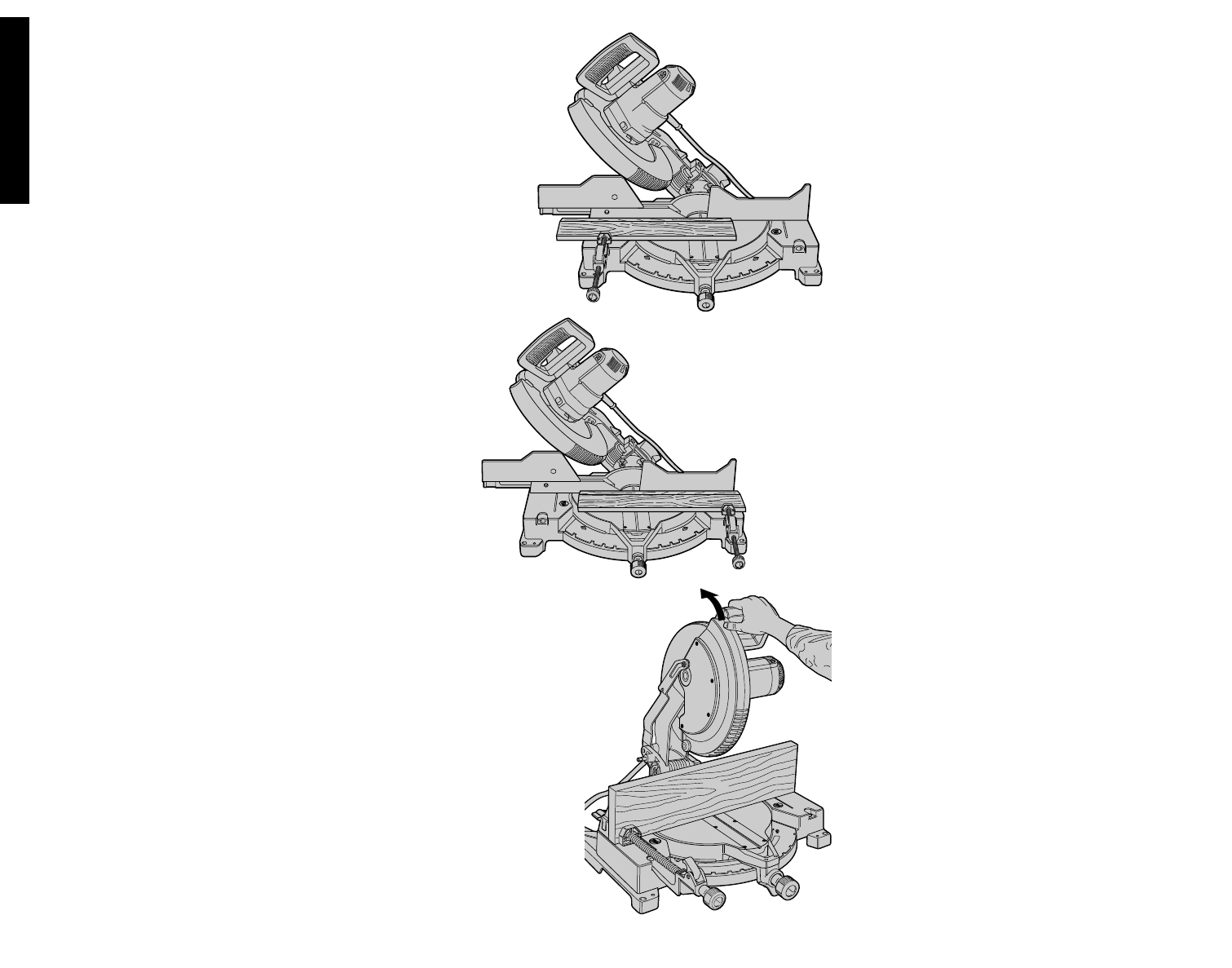
FIG. 23
FIG. 24
FIG. 25
A
L
W
A
Y
S
A
D
J
U
S
T
F
E
N
C
E
P
R
O
P
E
R
L
Y
B
E
F
O
R
E
U
S
E