


English
5
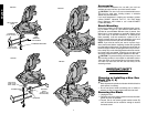
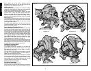
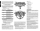
4. Depress the spindle lock button (Fig. 3) while carefully
rotating the saw blade by hand until the lock engages.
5. Keeping the button depressed, use the other hand and
the wrench provided (D) to loosen the blade screw.
(Turn clockwise, left-hand threads)
6. Remove the blade screw (E), outer clamp washer (F),
and blade (G). The 1" (25.4mm) blade adapter (H), if
used, and the inner clamp washer (I), may be left on
the spindle.
NOTE: For blades with a blade hole of 5/8" (15.88mm), the
1" (25.4mm) blade adapter is not used.
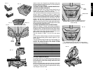
Installing a Blade
1. Unplug the saw.
2. With the arm raised, the lower guard held open and the
pivot plate raised, place the blade on the spindle, onto
the blade adapter [if using a blade with a 1" (25.4mm)
diameter blade hole] and against the inner clamp
washer with the teeth at the bottom of the blade point-
ing toward the back of the saw.
3. Assemble the outer clamp washer onto the spindle.
4. Install the blade screw and, engaging the spindle lock,
tighten the screw firmly with wrench provided. (Turn
counterclockwise, left-hand threads)
NOTE: When using blades with a 5/8" (15.88mm) diame-
ter blade hole, the blade adapter will not be used and
should be stored in a safe place for future use.
5. Return the guard bracket to its original position and
firmly tighten the guard bracket screw to hold bracket
in place.
WARNING:
• The guard bracket must be returned to
its original position and the screw
tightened before activating the saw.
• Failure to do so may allow the guard
to contact the spinning saw blade
resulting in damage to the saw and
severe personal injury.
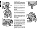
Installing Extension Kit
Side Table Extension (Some Models)
BE SURE TO OBSERVE ALL OF THE SAFETY
INSTRUCTIONS IN YOUR MITER SAW INSTRUCTION
MANUAL.
UNPLUG THE MITER SAW BEFORE INSTALLING,
ADJUSTING OR REMOVING THE EXTENSION KIT.
The extension kit can be used on either or both sides of the
saw. The supplied extension kit is factory installed on the
left side:
1. Install the self-tapping stud into the hole underneath
the saw.
2. Install extension tube making sure the clamping brack-
et will catch the legs.
3. Tighten clamping bracket against the legs.
45
5
5
40
3
5
50
4
5
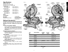
FIG. 4
LOCK
DOWN
PIN
FIG. 5
G
F
E
DISTANCE FROM
BLADE MUST BE
EQUAL
I
FIG. 6
A
H
WARNING: Do not lift, support, or carry the miter saw
by the extension kit. To do so may cause tipping and loss
of control, leading to personal injury.
NOTE: Before transporting the saw, remove the extension
or telescope it into the base.
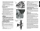
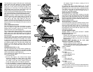
Rear Lower Guard Adjustment
Check the rear lower guard to ensure that it is located such
that the saw blade is in the center and equidistant from
each side, as shown in Figures 6 and 7. Adjust as neces-
sary by loosening the two screws and moving the guard.
Firmly tighten both screws. Never remove this guard.
Transporting the Saw
TURN OFF AND UNPLUG THE MITER SAW BEFORE
ATTEMPTING TO MOVE IT OR MAKE ANY ADJUST-
MENTS WHAT-SO-EVER!
In order to conveniently carry the miter saw from place to
place, a carrying handle has been included on the top of
the saw arm, as shown in Figure 3. To transport the saw,
lower the arm and depress the lock down pin shown in
Figure 4.
Adjustments
PERFORM ALL ADJUSTMENTS WITH THE MITER
SAW UNPLUGGED
NOTE: Your miter saw is fully and accurately adjusted at
the factory at the time of manufacture. If readjustment due
to shipping and handling or any other reason is required,
follow the steps below to adjust your saw.
Once made, these adjustments should remain accurate.
Take a little time now to follow these directions carefully to
maintain the accuracy of which your saw is capable.
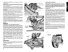
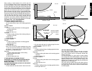
MITER SCALE ADJUSTMENT
Place a square against the saw’s fence and blade, as
shown in Figure 8. (Do not touch the tips of the blade teeth
with the square. To do so will cause an inaccurate meas-
urement.) Loosen the miter clamp knob (see Fig. 9) and
swing the miter arm until the miter latch locks it at the 0
miter position. Do not tighten the clamp knob. If the saw
blade is not exactly perpendicular to the fence, loosen the
three screws that hold the miter scale to the base (shown
in Fig. 9) and move the scale/miter arm assembly left or
right until the blade is perpendicular to the fence, as meas-
ured with the square. Retighten the three screws. Pay no
attention to the reading of the miter pointer at this point.
MITER POINTER ADJUSTMENT
Loosen the miter clamp knob and squeeze the miter latch
to move the miter arm to the zero position, as shown in
Figure 9. With the miter clamp knob loose allow the miter
latch to snap into place as you rotate the miter arm past
zero. Observe the pointer and miter scale through the
viewing opening shown in Figure 10. If the pointer does
not indicate exactly zero, gently pry it left or right using a
flat bladed screwdriver.
A
B
D