


Tighten the center nut. The 45º bevel stops require adjustment after the bevel square to table
adjustment is complete.
BEVEL POINTER (FIG. 8)
If the bevel pointers do not indicate zero, loosen each screw that holds each bevel pointer in
place and move them as necessary.
BEVEL STOP 45º RIGHT AND LEFT ADJUSTMENT (FIG. 8)
Your saw has two 45º bevel adjustments, one for the right, and one for the left. The procedure
is the same for each.
To align the 45º stops, lock the arm in the down position. Place a speed square against the
blade and table taking care to have the square not touch a blade tooth. Loosen the bevel lock
lever and ensure the bevel latch has firmly snapped into place at 45º. If the saw blade is not
45º to the table, loosen the nut which holds the 45 bevel latch plate to the table. Rotate the
adjustment screw counterclockwise one or two turns so that the blade is less than 45º to the
table. Turn the adjustment screw clockwise until the blade is 45º to the table. Tighten the lock
nut.
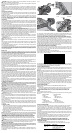
FENCE ADJUSTMENT (FIG. 9)
WARNING: To reduce the risk of serious personal injury, turn off the tool and
disconnect it from the power source before attempting to move it, change accessories
or make any adjustments accept as written in laser adjustment instructions.
In order that the saw can bevel to a full 48º left or right, one of the fences can be adjusted to
provide clearance. To adjust the fences, loosen a plastic knob and slide the fence outward.
Make a dry run with the saw turned off and check for clearance. Adjust the fence to be as
close to the blade as practical to provide max imum workpiece support, without interfering with
arm up and down movement. Tighten knob securely. When the bevel operations are complete,
don’t forget to relocate the fence.
NOTE: The guide groove of the fences can become clogged with sawdust. If you notice that it
is becoming clogged, use a stick or some low pressure air to clear the guide groove.
AUTOMATIC ELECTRIC BRAKE
Your saw is equipped with an automatic electric blade brake which stops the saw blade within
5 seconds of trigger release. This is not adjustable.
On occasion, there may be a delay after trigger release to brake engagement. On rare
occasions, the brake may not engage at all and the blade will coast to a stop.
If a delay or “skipping” occurs, turn the saw on and off 4 or 5 times. If the condition persists,
have the tool serviced by an authorized D
EWALT service center.
Always be sure the blade has stopped before removing it from the kerf. The brake is not
a substitute for guards or for ensuring your own safety by giving the saw your complete
attention.
GUARD ACTUATION AND VISIBILITY
CAUTION: Pinch Hazard. To reduce the risk of injury, keep thumb underneath the handle
when pulling the handle down. The lower guard will move up as the handle is pulled down
which could cause pinching.
The blade guard on your saw has been designed to automatically raise when the arm is brought
down and to lower over the blade when the arm is raised.
The guard can be raised by hand when installing or removing saw blades or for inspection
of the saw. NEVER RAISE THE BLADE GUARD MANUALLY UN LESS THE SAW IS TURNED
OFF.
NOTE: Certain special cuts of large material will require that you manually raise the guard. Refer
to Cutting Large Material under Special Cuts.
The front section of the guard is louvered for visibility while cutting. Although the louvers
dramatically reduce flying debris, they are openings in the guard and safety glasses should
be worn at all times when viewing through the louvers.
KERF PLATE ADJUSTMENT
To adjust the kerf plates, loosen the screws holding the kerf plates in place. Adjust so that the
kerf plates are as close as possible without interfering with the blade’s movement.
RAIL GUIDE ADJUSTMENT
Periodically check the rails for any play or clearance. The right rail can be adjusted with the set
screw shown in Figure 4. To reduce clearance, use a 4 mm hex wrench and rotate the set screw
clockwise gradually while sliding the saw head back and forth. Reduce play while maintaining
minimum slide force.
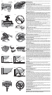
MITER LOCK ADJUSTMENT
The miter lock rod should be adjusted if the table of the saw can be moved when the miter lock
is locked down. To adjust the miter lock handle, put the miter lock handle in the up, unlocked
position. Using a 13 mm open end wrench, loosen the lock nut on the miter lock rod (Fig. 10).
Using a slotted screwdriver, tighten the miter lock rod by turning it clockwise as shown in
Figure 10. Turn the lock rod until it is snug, then turn counterclockwise one turn. To ensure the
miter lock handle is functioning properly, re-lock the miter lock to a non-detented measurement
on the miter scale – for example, 34º – and ensure the table will not rotate. Tighten lock nut.
Brushes
WARNING: To reduce the risk of serious personal injury, turn off the tool and disconnect
it from the power source before attempting to move it, change accessories or make any
adjustments accept as written in laser adjustment instructions.
Inspect carbon brushes regularly by unplugging tool, removing the motor end cap (Fig. 4), lift
the brush spring and withdraw the brush assembly. Keep brushes clean and sliding freely in
their guides. Always replace a used brush in the same orientation in the holder as it was prior to
its removal. Carbon brushes have varying symbols stamped into their sides, and if the brush is
worn down to approximately 1/2" (12.7 mm), the spring will no longer exert pressure and they
must be replaced. Use only identical D
EWALT brushes. Use of the correct grade of brush is
essential for proper operation of electric brake. New brush assemblies are available at D
EWALT
service centers. The tool should be allowed to “run in” (run at no load) for 10 minutes before
use to seat new brushes. The electric brake may be erratic in operation until the brushes are
properly seated (worn in). Always replace the brush inspection cap after inspection or servicing
the brushes.
While “running in” DO NOT TIE, TAPE, OR OTHER WISE LOCK THE TRIGGER SWITCH ON.
HOLD BY HAND ONLY.
Controls
Your compound miter saw has several main controls, which will be discussed briefly here. For
more information on these controls, see the respective sections earlier in the manual.
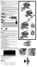
MITER CONTROL (FIG. 7)
The miter adjustment/lock handle and detent trigger allows you to miter your saw to 60° left
and 50º right. To miter the saw, lift the miter adjustment/lock handle, push the miter latch button
and set the set the miter angle desired on the miter scale. Push down on the lock handle to
lock the saw table in place.
TRIGGER SWITCH
The trigger switch (Fig. 4) turns your saw on and off. A hole is provided in the trigger for
insertion of a padlock to secure the saw.
MITER LATCH OVERRIDE (FIG. 7)
The miter latch override allows your saw to override the common stop angles. To override the
common stop angles, push the miter latch button and flip the miter latch override lever to the
vertical position.
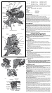
BEVEL CONTROL (FIG. 4, 8)
The bevel latch levers and bevel lock handle allow you to bevel the saw to 48º left and right.
Your saw has two bevel latch levers, one on either side of the rear support housing. Only one
needs to be used to move the bevel to either direction. The bevel lock handle is on top of the
rear support housing. To bevel the saw, loosen the bevel lock handle. Lift one of the levers to
approximately 45º and set the bevel angle desired on the bevel scale. Two bevel scales are
provided for convenience. Lock the bevel lock handle to lock the bevel in place. The bevel latch
levers can be lifted vertically to override the common stop angles.
The bevel lock handle is designed to have a limited rotation amount. The handle can be
reoriented to compensate for normal wear. The bevel lock handle should be reoriented if the
bevel of the saw can be moved when the bevel lock handle is tightened. To adjust the bevel
lock handle, remove the screw in the center of the handle. Carefully pry off the handle using
a flat bladed screwdriver. Reorient and install the handle such that it will hold the bevel when
tightened. Install and tighten screw.
RAIL LOCK KNOB (FIG. 4)
The rail lock knob allows you to lock the saw head firmly to keep it from sliding on the rails. This
is necessary when making certain cuts or when transporting the saw.
GROOVING STOP (FIG. 4)
The grooving stop allows for groove cutting. Flipping the lever toward the front of the saw and
adjusting the thumbscrew changes the depth of the groove cut. Flipping the lever toward the
rear of the saw bypasses the grooving stop.
HEAD DOWNLOCK PIN (FIG. 4)
To lock the saw head in the down position, push the head down, push the pin in and release
the saw head. This will hold the saw head safely down for moving the saw from place to place.
To release, press the saw head down and pull the pin out.
OPERATION
WARNING: To reduce the risk of serious personal injury, turn off the tool and disconnect
it from the power source before attempting to move it, change accessories or make any
adjustments accept as written in laser adjustment instructions.
FIG. 9
FENCE KNOB
(ONE EACH SIDE)
BLADE
WRENCH
FIG. 10
MITER LOCK
ROD
LOCK NUT
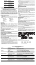
PROPER CUT
FIG. 13A
IMPROPER CUT
FIG. 13B
FIG. 12
FIG. 11
FIG. 14
FIG. 16
ANGLE “A”
FIG. 17
FENCE
TABLE
CROWN MOLDING FLAT ON TABLE
AND AGAINST FENCE
CROWN MOLDING BETWEEN
FENCE AND TABLE
TABLE
FENCE
BOTTOM SIDE
OF MOLDING
TOP SIDE
OF MOLDING
FIG. 18
DW 7084
CROWN
MOLDING
FENCE
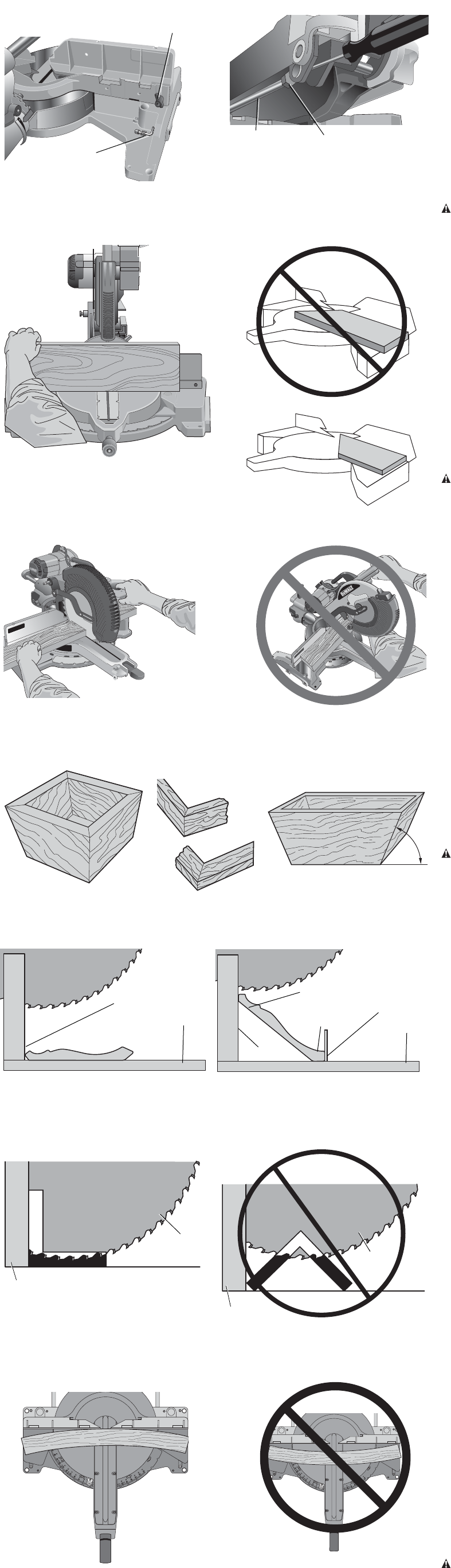
FIG. 21
RIGHT
FIG. 22
WRONG
A
FIG. 15
B
A
FIG. 19
BLADE
FENCE
RIGHT
WRONG
FIG. 20
BLADE
FENCE