


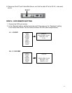
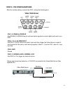
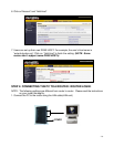
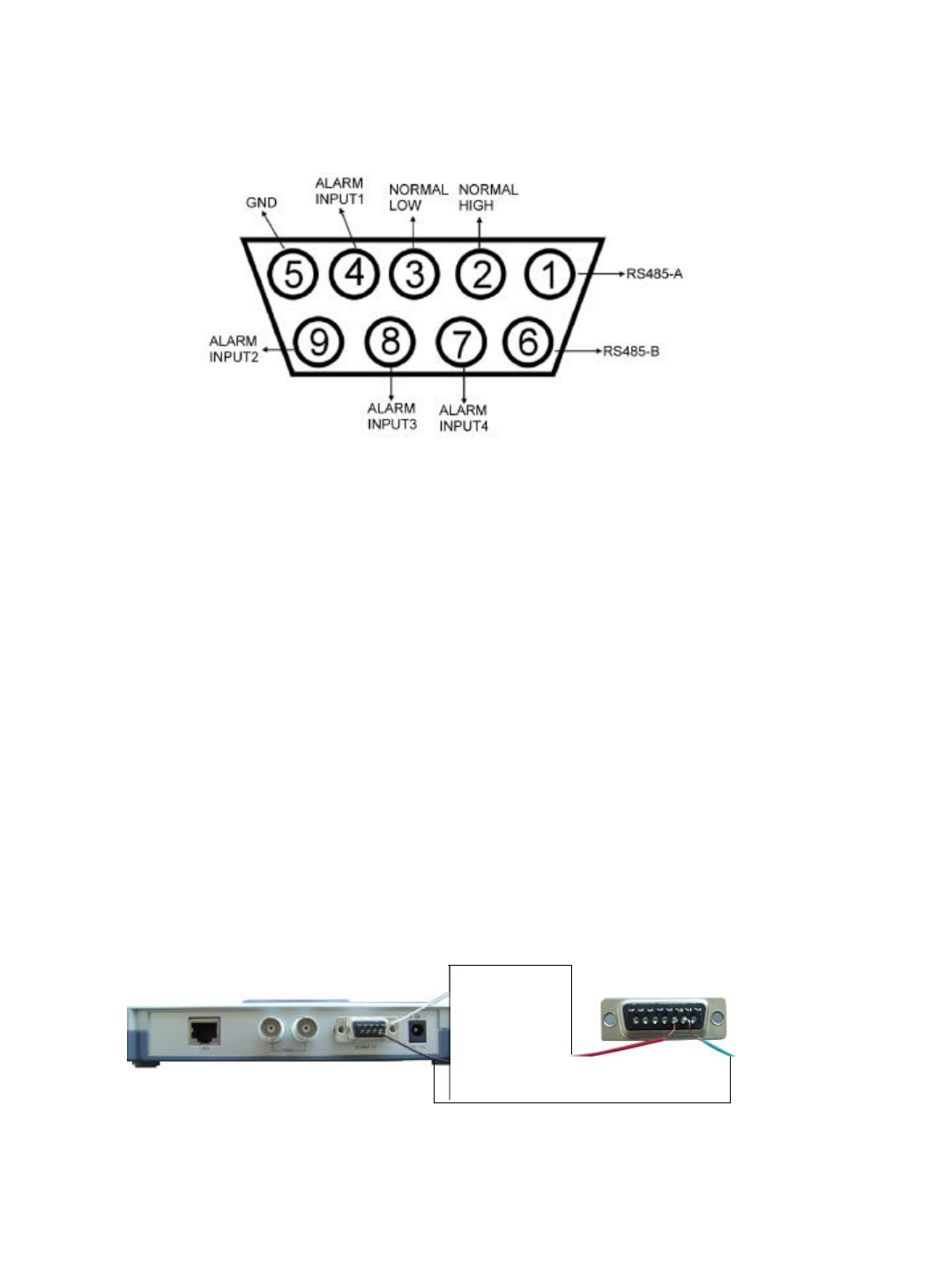
STEP 5: PIN CONFIGURATIONS
After the remote setting, connect the DVR, noting the following pins.
PIN 1, 6. RS485-A, RS485-B
Use RS485-A & RS485-B serial communication signals to control digital units such as a
DVR.
PIN 4, 7, 8, 9. ALARM INPUT
Use PIN 4,7,8,9 to receive the alarm input and then trigger the Video Server to send E-
mail to users for the auto e-mail warning system. (Alarm 1, 2 are for CH1; alarm 3, 4 are
for CH2)
PIN 5. GND
Ground
PIN 2, 3. NORMAL HIGH, NORMAL LOW
Use PIN 2 or 3 to trigger an external device.
-12-
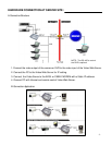
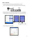
Video Web Server
RS485-B
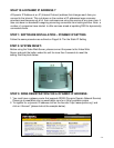
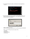
Please see the picture below for a 1CH DVR connected to the Video Web Server.(See
Appendix #1)
RS485-A
Pin 1
Video Web Server
1 CH DVR
Pin 6
Pin 10
Pin 11