


For use with 1/2” or less sand-
ing and grinding stone acces-
sories only.
Attachment for use with Dremel Rotary Tool
Models 100, 200, 300, 400, 4000, 770, 800,
275, 285, 395, 398.
The guide comes completely assembled and
ready to use for sanding and grinding applica-
tions up to ½” ( 13 mm) thick.
Router bits are not allowed for
use with the Sanding/Grinding
Guide attachment.
Sanding/Grinding Guide Attachment
Installation instructions:
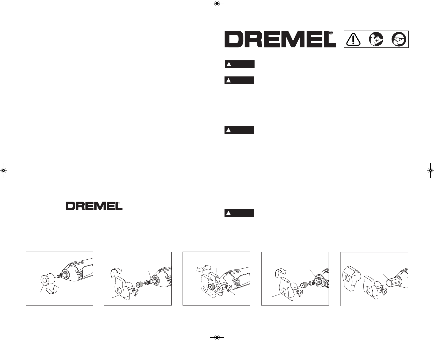
Step 1: Remove the housing cap A from the
end of the tool and set housing cap aside. The
original housing cap must be reinstalled when
this attachment is not used (Fig. 1).
Step 2 & 3: Loosen the collet nut and place your
accessory in and tighten. Note:The attachment
is for ½” diameter accessories or smaller.
Please refer to the owner's manual for proper
collet nut assembly instructions and accessory
operation instructions.
When inserting a bit into your
Dremel Rotary Tool be sure
that the bit is securely inserted into the collet. Al-
ways use the wrench to tighen the collet nut to
prevent the bit from loosening within the collet.
Do not use the Dremel Chuck.
Step 4: Thread the attachment B onto the
threaded portion of the housing collar C(Fig. 2).
Step 5: Adjust the attachment B to the desired
depth by loosening the wing knob D (Fig. 3).
Using the Sanding/Grinding Guide
Attachment
The guide has a 90 and 45 degree bevel for var-
ious sanding applications. The tool with the
guide attached can be taken to a secure work
piece or can be stationary in the Dremel Multi-
Vise.
Installation instructions to Dremel
Multi-Vise:
The tool with the guide attached can be taken
to a secure workpiece or can be stationary in the
Dremel Multi-Vise 2500-01 (Sold Separately).
Step 1: Set up Dremel Multi-Vise on secure
workbench. Place the tool holder into the
Dremel Multi-Vise according to Dremel Multi-
Vise instructions.
Step 2: Place tool with accessory secure
through the tool holder F (Fig. 4).
Step 3:Hold the Sanding/Grinding Guide Bfirm
and thread onto front end of tool until tightly
secure (Fig. 4).
Step 4: The guide can be adjusted from the 90
degree side to the 45 degree side by loosening
the wing nut D and sliding the attachment B off
the cylinder E (Fig. 5).
Step 5:Turn the attachment B180 degrees and
slide the attachment B onto the cylinder E and
tighten wing knob D at desired depth (Fig. 5).
Read and understand the manual for the use of the tool with this accessory.
SAVE THESE INSTRUCTIONS
!
WARNING
Sanding/Grinding Guide Attachment Model A576
!
WARNING
!
WARNING
!
CAUTION
A
D
FIG. 1
FIG. 2
FIG. 3
B
C
B
2610958467 04/09 Printed in Mexico
P.O. Box 1468
Racine, Wisconsin 53401
1-800-437-3635
http://www.dremel.com
FIG. 5
E
FIG. 4
F
B
DM 2610958467 04-09:DM 2610958467 04-09 4/22/09 12:52 PM Page 1