


Dukane Manual Part No. 403-570-01
Page 97
Appendix A
1
1
6
6
9
9
5
5
Pin
Signal Description
Left Optical Switch Output
1
Right Optical Switch Output
2
+24 VDC Switched by E-Stop
3
Abort Signal
4
Ground
5
Ground
6
Ground
7
Automation Input
8
+24 VDC Power
9
(Power OFF when Abort switch pushed)
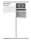
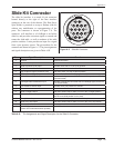
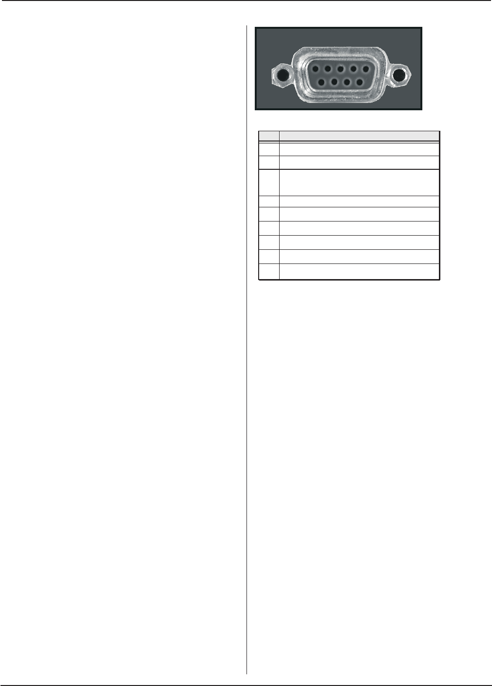
Base Interface
Connector
The base interface connector is a DB 9–socket connector.
A closeup of the base connector is shown in Figure 2–2,
and a closeup of the rear thruster connector is shown
in Figure 3–8. The pin numbers for the connector are
shown in Figure A–1. The pin assignments and signal
descriptions are given in Table A—I.
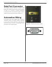
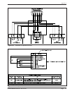
A schematic of the Operate and Abort switches
connected through the base Interface Connector is
shown in Figure A-5.
Figure A–1 Base Interface Connector
Table A-I Pin Assignments and Signal Description
for the Base Interface Connector