


Dukane Manual Part No. 403-570-01
Page 25
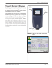
Section 4 - Display and Controls
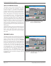
Dimly Lit
Red LED
Brigtly Lit
Red LEDs
1
1
6
6
9
9
5
5
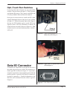
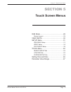
Opti–Touch Run Switches
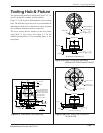
Located on either side of the base are two optical RUN
switches. These are shown in Figure 4–3. These switches
use Infrared (IR) sensors. They comply with OSHA and
CE safety standards. Both switches are identical.
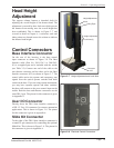
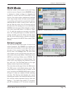
Each optical–touch switch has a small red LED which
is dimly illuminated whenever the power is on, as shown
in Figure 4–5. When the operator places their nger in
the tray, the LED brightens and a second LED in the
opposite corner of the tray illuminates to indicate the
switch has been activated as shown in Figure 4–6. Both
switches must be activated simultaneously to initiate a
weld cycle.
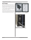
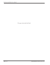
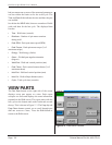
Data I/O Connector
A connector for output data is provided on the rear of
the welder above the power switch. This connector is a
female type DB-9 as shown in Figure 4–7. It provides a
computer connection to export part data, motor load and
position proles. A pinout of the Data I/O connector is
provided in Appendix A. Detailed information on the
data that can be obtained from the welder is given in
Chapter 8.
Figure 4–5 Right Operate Switch in Standby
Mode, One LED Dimly Lit
Figure 4–6 Right Switch in Operate Mode, Both
LEDs Brightly Lit
Figure 4–7 DB–9 Data I/O Connector