


Dukane Manual Part No. 403-570-01
Page 29
Section 5 - Touch Screen Menus
RUN Mode
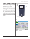
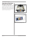
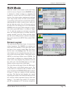
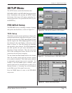
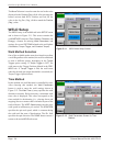
When the welder is rst turned on after the E-Stop
switch is reset (see Figure 4-4), the STARTUP screen
is displayed as shown in Figure 5–1 directing the
operator to Activate both RUN SWITCHES to reset
machine. Press both switches simultaneously and hold
until a beep sounds, which will take several seconds.
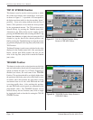
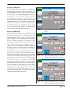
A second beep will sound a few seconds after the rst,
indicating that the welder is ready to run a weld cycle
(the bar under the smiley face will become green at
the same time). The message area is now clear and the
STATUS icon in the upper left has changed to a smiley
face with a green band below it as shown in Figure
5–2. If, when the switches are activated as described
above, the tooling hub begins to oscillate instead of
rotating smoothly, press the E-Stop and then check
that the correct tooling inertia is entered as described
later in this manual in the SETUP Menu (under TOOL
SETUP).
Screen Layout
The screen has the same basic layout for most of the
selected operations. The
STATUS
icon indicates the
ready state of the machine. To the right of the icon is
the name of the currently loaded
Setup File
. Below
the le name is the
Message Area
. The three mode
select buttons on the left side below the status icon
select either a
Run mode (RUN), a Weld Setup screen
(SETUP), or the Setup Utilities screen (TOOLS). The
selected mode is indicated by a darkened button. The
center of the screen displays the parameters from the
last weld cycle. The Part Data button on the right
displays a report of previously welded parts.
The screen shots on this page all show the RUN mode.
The RUN screen is the default startup screen. This
screen needs to be selected in order to initiate a weld
cycle. Just below the PROCESS DATA label as shown
in Figure 5-2, there are a number of elds containing
part data.
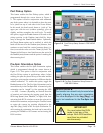
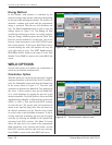
The
Part Nr
. eld identies the current
sequential part number. The
Limits
eld indicates if the
last weld was within programmed process limits and
displays “–” if no limits were violated, “
S
” for suspect
part, “
B
” for a bad part, or “
E
” for an error. A suspect or
Figure 5–1 Startup Screen With E-Stop Cleared
Figure 5–2 Run Mode Screen With Welder Reset