


Dukane Manual Part No. 403-570-01
Page 51
Section 6 - Machine Operation
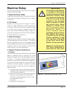
IMPORTANT
The Dual Servo Spin Welder
is capable of developing
substantial torque and high
rotational velocity. Keep
your hands and body away
from the tool head during
operation. The spinning
head is capable of inict-
ing serious injury. Never
attempt to retrieve a part
from a spinning tool head.
A l w a y s w e a r a
f a c e s h i e l d w h e n
operating the Dual Servo
Spin Welder. Be extreme-
ly careful not to let long
sleeves, necklaces or long
hair become entangled
in the Dual Servo Spin
Welder during operation.
Always turn machine power
OFF when instalaling or
removing the spin tool.
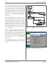
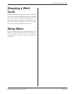
ABOR
T
PO
W
ER
IN CYCLE
Tw
i
st to Reset
Tw
ist to Reset
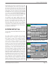
Machine Setup
The startup procedure given here is for a new machine
that has just been installed.
1. Base Interface Cable
Attach the base interface cable from the rear of the base
to the back of the thruster housing as shown in Figures
3–7 and 3–8.
2. AC Power
Insert the AC power plug (refer to Figure 3–4) into a
240 VAC, 1–Phase NEMA type 6–20R receptacle rated
at 20 Amps. The correct style outlet is shown in Figure
3–5. Do not alter the plug or receptacle in any way.
Refer to the section on Electrical Safety in Chapter 2 if
you have any questions. Ensure the AC Power Switch is
in the OFF position (see Figure 3-6).
3. Attach Tooling
Attach the upper tooling to the hub and torque tightly.
The hub dimensions are given in Figure 3-2. The slot in
the hub is intended to accept a ¼-inch standard dowel
pin assembled to the upper tool for repeatable mounting
orientation. Place the lower xture on the base and
attach it loosely so it can be aligned later.
4. Adjust Thruster Position on
Column
The rear support column of the Dual Servo Spin Welder
features a threaded shaft for adjusting the overall
height of the thruster head. The adjustments are shown
in Figure 3-7. The thruster height should be adjusted
properly to ensure that the weld head has enough travel
to perform the weld (within the 5-inch stroke limit),
and that the welded assembly can readily be removed
from the tooling. To adjust the position, complete the
following steps:
a) Loosen the three rear nuts (which lock the head
assembly in place). The nuts are 22mm wide, but
a 7/8-inch socket will also t.
b) Raise or lower the head by turning the adjustment
lead screw on top, which is also a 22mm hex.
The lead screw has 8 threads per inch, so 1 turn
moves the head 1/8-inch
(3.18 mm).
c) Tighten the rear locking nuts.
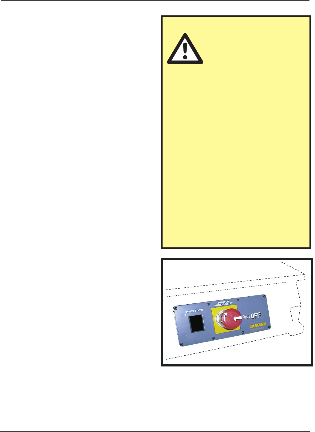
Figure 6–1 Setting and Resetting the E–Stop