


Dual Servo Spin Welder User’s Manual
Dukane Manual Part No. 403-570-01Page 52
5. Reset E-Stop
Reset the emergency stop button by turning clockwise.
Refer to Figure 4-4. The status display on the base will
change from ABORT in red to POWER in green.
6.Turn Power ON
Turn on the AC power switch.
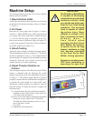
7. Set Tool Parameters
On the touch screen, press the SETUP button. Press
Enter on the ENTER SECURITY CODE screen if
no password has been previously set, or type in the
password and then Enter. Press the TOOL Setup button
and enter the TOOL Inertia (kg*cm^2) and TOOL Weight
(kg). Press the RUN button and wait until the
PLEASE
WAIT
… indicator above it disappears.
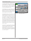
8. Initialize (Home) Welder
The touch screen will now instruct you to
Activate both
RUN SWITCHES to reset machine
. This is illustrated
in Figure 5–1. Once the switches are activated, both
servos will rst move to their respective home positions
(corresponding to internal encoder reference pulses
in each servo). Then the spin motor will rotate to the
programmed nal weld orientation set in the SETUP
> WELD tab > Orientation > Weld eld (Figure 5-17),
and the press will move to position set in the SETUP >
PRE-WELD tab > TOP OF STROKE Position > Position
(mm) eld (Figure 5-8). The switches can be deactivated
once a beep sounds. The homing procedure is complete
after the second beep sounds and the indicator directly
below the yellow face icon becomes green.
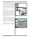
9. Align Lower Fixture with Spin
Tool
Place a set of parts in the upper tool and lower xture.
Navigate to the SETUP > TRIGGER Position menu,
press the DOWN button, and select Me or Hi in VERT.
Jog Speed. Jog the press head down to a position where
the weld joint can be used to align the lower xture by
activating both RUN SWITCHES. Change the vertical
jog speeds as needed and use the UP button to move
the head up if desired. When nished, press the DONE
button and remove the parts.