


Copyright © 2011 Eagle Tree Systems, LLC
http://www.eagletreesystems.com
Instruction Manual for the 3 Axis G-Force MicroSensor
Model Numbers: GFORCE-LOW, GFORCE-HIGH
Document Version 1.2
Thank you for your purchase! This instruction manual will guide you through the installation and operation of your G-Force MicroSensor
(the G-Sensor). The latest version of this manual is available in the Product Manuals section of the Support tab on
http://www.eagletreesystems.com. The online manual includes any updates that were made after this manual was printed. Please read the
entire manual carefully before proceeding.
Packing List
Your package should include the following: The G-Sensor, the Standalone Cable, and a printed version of this manual.
Intended Uses
The G-Sensor is intended exclusively for recreational use in radio control models and model rockets. Other uses are not supported.
Further, using the G-Sensor in situations where its use or failure could result in loss of life, bodily injury or property damage is
expressly prohibited.
Want to use the G-Sensor for your own hardware/firmware project? Read on in the manual for more information!
Have questions or Feedback?
Eagle Tree is committed to providing great customer service. If you’ve read the manual and something is not clear, just ask. We’d much
prefer to take the time to answer your questions, rather than having you waste your valuable time struggling with an issue.
To get help, visit the Eagle Tree G-Sensor support thread at http://www.rcgroups.com/forums/showthread.php?t=1454098. Chances are
someone has posted a solution to your problem already. If not, posting your problem there will get a very quick response from the Eagle Tree
community. If you prefer to not post on the forum, or you feel there is a problem with your Eagle Tree hardware, please open a support ticket
with us at http://ticket.eagletreesystems.com
What the G-Sensor Does
The G-Sensor is a precision 3 axis accelerometer that constantly measures change in acceleration in the X, Y and Z axes. The unit of
acceleration measurement is the “g,” which equals the force of gravity (9.81 m/s
2
). So, when the G-Sensor reads 2 g, for example, this
equals 2 times the force of gravity.
The GFORCE-LOWG model measures and records acceleration to at least +/- 7 g in each axis. The GFORCE-HIGHG model measures to
at least +/- 38 g in the X and Y axes, and to at least +/- 7 g in the Z axis. The readings may be inaccurate if these values are exceeded.
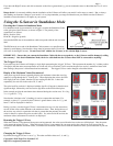
When used standalone, the G-Force sensor repeatedly displays the maximum acceleration encountered in each of its 3 axes, on the built in 7
segment LED display. These maximum values are stored to non-volatile memory, so when power is disconnected they are preserved.
Additionally, the G-Sensor can be connected to your eLogger V4 or V3 to provide acceleration data for your entire flight. When connected
to the eLogger, the acceleration in each axis can be displayed and graphed using the eLogger’s Windows software. NOTE: the G-Sensor is
NOT compatible with our prior eLogger V1 or V2 or our Data Recorder products.
Installing the G-Sensor in your Model
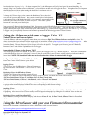
The G-Sensor can be mounted with double sided tape, Velcro, or similar. The G-Sensor is normally mounted flat in the model, with the label
down, and the “Y” arrow on the label facing toward the direction of travel. When mounted this way, the Y axis points in the direction the
model travels, the X axis is horizontally perpendicular to the direction that the model travels, and the Z axis points toward the top of the
model (normally toward the sky). With this mounting configuration, acceleration in the forward direction will show up as positive Y values,
and acceleration in the up direction will result in positive Z values. Note that the force of gravity is 1G, normally in the direction of the Z
axis.