


20
ENGLISH
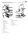
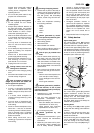
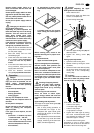
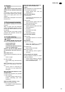
7.4 Fence guide extrusion
installation
• Fasten the fence guide extrusion
(40) with four each thumb screws
and washers to the saw table.
7.5 Rip fence installation
The rip fence can be used on both sides
of the blade.
1. Fasten the fence extrusion (41),
using
− two each pan-head screws,
− two each washers and
− two each knurled nuts
to the fence guide.
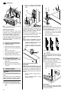
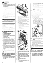
2. Attach the thus assembled rip fence
with one each
− pan-head screw,
− washer and
− wing nut
to the fence guide extrusion (42).
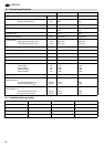
Rip fence alignment
1. Loosen the two small knurled nuts
(43) approx. one turn.
2. Turn the large knurled thumb screw
(44) as required to set the rip fence
square against the saw table.
3. Tighten both small knurled nuts (43)
again.
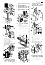
Scale installation
• Affix the self-adhesive scale (45) on
the fence guide extrusion, so that
the zero position is opposite of the
band saw blade. For an exact align-
ment set the rip fence against the
saw blade.
7.6 Dust collector connec-
tion
A
Danger!
Some types of saw dust (e.g. of
oak, beech and ash wood) can cause
cancer when inhaled: always use a
dust collector when working indoors
(required air speed at the saw's suc-
tion connector ≥ 20 m/s).
A
Caution!
Operation without a dust col-
lector is only possible:
− outdoors;
− for short-term operation
(up to 30 minutes maximum);
− with dust respirator.
− If no dust collector is used chips
will accumulate, which need to be
removed periodically.
Connect dust collector or industrial vac-
uum with a suitable adaptor to the dust
extraction port.
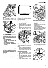
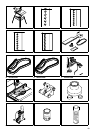
7.7 Band saw blade tension-
ing
A
Danger!
Too much tension can cause
the band saw blade to break.Too little
tension can cause the driven band
saw wheel to slip and the band saw
blade to stop.
1. Raise upper blade guide fully (see
“Operation”).
2. Check tension by pushing with a fin-
ger, halfway between table and
upper blade guide, against the side
of the blade. The blade should flex
not more than 1-2 mm.
3. Correct tension if necessary:
− turning the setting knob (46)
counter-clockwise increases the
blade tension.
− turning the setting knob (46)
counter-clockwise reduces the
blade tension.
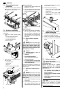
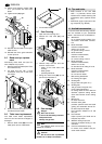
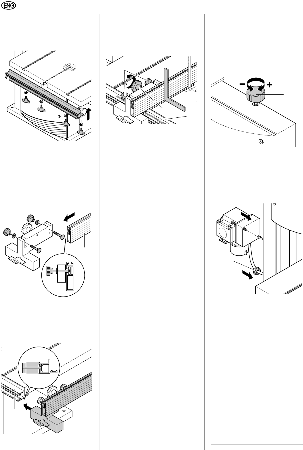
7.8 Installation of the combi-
nation switch/plug
1. Fit cable bushing (47) in the hole
provided in the band saw frame.
2. Fasten the combination switch/plug
with two screws to the band saw
frame.
7.9 Mains connection
B
Danger! High voltage
Operate the band saw in dry
surroundings only.
Operate the saw only on a power
source matching the following
requirements (see also “Technical
specifications”):
− fuse protection by a residual cur-
rent operated device (RCD) of
30 mA sensitivity;
− outlets properly installed, earthed
and tested;
− Three-phase outlets with neutral
wire installed;
3
Note:
Check with your local Electricity
Board or your electrician if in doubt
whether your house service connection
meets the requirements.
40
41
42
2
2
3
3
4
4
5
5
43
44
45
46
47